
Specifications


5 CAN I/O Support for FIFO
5-40
Examples
Example 1
Lets start with a simple model using the FIFO Setup block, FIFO Write block,
FIFO Read block, and FIFO Read Filter block. The entire CAN network
consists of a single physical connection between CAN port 1 and port 2
(loop-back configuration). For this, both CAN ports have to be terminated
properly.
The objective of the application is the following:
•Send a message with extended identifier 5100 and change data every
millisecond on port 1
•Send a message with standard identifier 112 and change data every even
millisecond on port 1
•Send a message with standard identifier 114 and change data every odd
millisecond on port 1
•Read 3 events every millisecond from the receive FIFO on port 2
•Display the incoming data of the 3 messages separately
•Acceptance filtering is not used (all messages are accepted)
The data transmitted with the CAN messages are double values in all the
following examples. This has been chosen for simplicity. You should refer to the
bit-packing and bit-unpacking chapter of the standard CAN driver
documentation, on how to construct from respectively extract into bit fields.
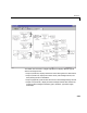
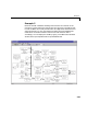
The first implementation uses the following scheme.
The matrix signal entering the FIFO Write block consists of all three messages
including the Control element (sixth element), therefore the matrix size will be
[3,6]. The sample time of the FIFO Write block is defined as 1 ms. For the
standard identifiers which have to be sent out every other millisecond, the
Control element is alternated accordingly. This is achieved by using a Unit
delay block with corresponding feedback as the Control element value.
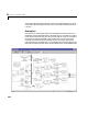
The FIFO Read block has a Read depth of 3 and also a base sample of 1 ms.
Three FIFO filter blocks are connected to the output of the FIFO read block (in
parallel) to extract the information of the incoming CAN messages. You can
display the model by typing, in the MATLAB command window, either
xpccanpcififo1.mdl or xpccan104fifo1.mdl.