
Specifications


CAN FIFO Driver Blocks for the CAN-AC2-104 with Philips SJA1000 CAN-Controller
5-27
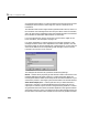
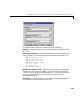
The board allows activating proper termination for each of the two CAN ports
separately by means of DIP-switches at the rear panel of the board. Refer to the
Softing user manual on how the DIP-switches have to be set. Both CAN ports
have to be terminated properly where you use the provided loop-back model in
order to test the board and drivers.
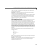
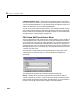
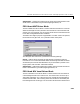
FIFO Write Driver Block
The FIFO Write driver block is used to write CAN messages into the transmit
FIFO. The firmware running in FIFO mode will then process the information
found in the transmit FIFO and finally put the constructed CAN messages onto
the bus.
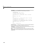
The block has one input port of type double. At this port all necessary
information has to be provided in order to construct valid CAN messages to be
written into the transmit FIFO. For each CAN message 5 elements have to be
passed, which are
Port
Identifier
Identifier type
Data frame size
Data
Port — The value can be either 1 (port 1) or 2 (port 2) and defines at which port
the CAN message will be sent out from.
Identifier — This is the identifier of the CAN message to be sent out. If it is a
Standard CAN message the valid range is 0 to 2047, if extended the range is 0
tp 2
29
-1.
Identifier type — The value can be either 0 (Standard identifier range) or 1
(Extended identifier range) and defines the identifier type of the outgoing CAN
message.
Data frame size — The value can be in the range of 0 to 8 and defines the data
frame size in bytes of the outgoing CAN message
Data — This is the data for the data frame itself and is defined as a double
value (8 bytes). The CAN packing block is used to construct the data as a double
value.
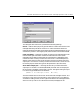
Because all this information can be dynamically changed in FIFO mode during
application execution, the information is provided at the block input instead of