
Specifications


5 CAN I/O Support for FIFO
5-12
each row of the matrix signal defines one CAN message and each row combines
the 5 elements of information defined above (in this order).
For more on how to construct the correct matrix signal for the FIFO write
block, see See “Examples” on page 5-40.
For certain applications it may be necessary to make the writing of a CAN
message into the transmit FIFO dependent on the model dynamics. For this
case, the matrix signal can also be of dimension n*6 instead of n*5. In this case,
the sixth column defines if the corresponding CAN message is written into the
transmit FIFO (value 1) or not (value 0).
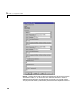
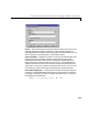
The dialog box of the block lets you define the following settings.
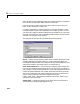
Board — Define which physically present board is used to send out the CAN
messages defined by this block instance. For more information about the
meaning of the board number see the Setup driver block described above. If just
one board is present in the target system, you should select 1.
Show status output port — Check this box to enable the status output port.
If the box is unchecked, the block does not have an output port. If enabled, a
port is shown. The signal leaving the block is a vector of type double where the
number of elements depends on the signal dimension of the block input port.
There is one element for each CAN message written into the transmit FIFO
and the value is identical to the return argument of function
CANPC_send_data(…) described in the Softing user manual. Refer to that
manual for more information.
Sample time — Defines the sample time at which the FIFO Write block is
executed during a model (target application) run.