
Specifications


4 CAN I/O Support
4-50
Model execution driven by CAN-messages (Interrupt
capability of CAN Receive blocks)
In certain application it is necessary that the model (target application)
execution is driven by the pace of an incoming CAN message. The standard
behavior of the xPC Target kernel is to drive the model (target application) in
time monotonic fashion (time interrupt), but allows to replace the driving
interrupt by any other hardware interrupt. Because the three supported
CAN boards allow to fire a hardware interrupt upon reception of a specific
CAN message, the timer interrupt line in the kernel can be replaced by the
interrupt line assigned to a CAN board. This leads to a CAN message driven
execution of the target application.
To set this up, two independent steps are necessary.
1 The timer interrupt line in the kernel setup has to be replaced by the board’s
hardware interrupt line.
2 The CAN Setup and CAN Receive blocks have to be properly set up.
Both steps are slightly different for each of the three supported CAN boards.
Therefore the two steps are explained for each board type below.
CAN-AC2 (ISA)
The CAN-AC2 is an ISA-board, and the hardware interrupt line is set by means
of hardware jumpers on the board. Refer to the Softing user manual of the
board on how to set a certain interrupt line. Select an interrupt line, which is
not used by any other hardware device in the xPC Target system (for example
by the Ethernet card).
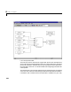
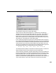
1 In the Simulink window, and from the Tools menu, point to Real-Time
Workshop
, and then click Options. Select the category “xPC Target code
generations options” in the displayed dialog box. In the “Real-Time
Interrupt Source” popup menu select the interrupt line number which you
have set by the jumpers on the board. Close the dialog box and save the
model.
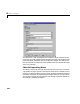
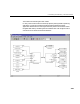
2 Open the dialog box of the CAN Receive block in the model which defines the
CAN message (identifier) to be used to fire the interrupt. Check the