
Specifications

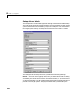


CAN driver blocks for the CAN-AC2-104 (PC/104) with Philips SJA1000 CAN-Controller
4-33
board number depends on the I/O Base Address edit field described further
below. If just one board is present in the target system, board number 1 should
be selected.
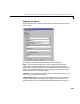
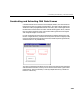
CAN 1 - Baud rate — The second control (popup menu) lets you define the most
common baud rates for CAN port 1. If special timing is necessary (baud rate),
the value
CAN 1 - User defined baud rate can be selected. In this case the
third control (edit field) is used to provide the four values for the timing
information. The vector elements have the following meaning
[ Prescaler, Synchronisation-Jump-Width, Time-Segement-1,
Time-Segment-2 ]
For more information about these values see the Softing user manual for this
board.
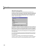
CAN 1 - Baud rate — The fourth control (popup menu) lets you define the most
common baud rates for CAN port 2. If special timing is necessary (baud rate),
the value “User defined” can be selected. In this case the fifth control (edit field)
is used to provide the four values for the timing information. The vector
elements have the following meaning
[ Prescaler, Synchronisation-Jump-Width, Time-Segement-1,
Time-Segment-2 ]
For more information about these values see the Softing user manual for this
board.
Initialization and Termination — The sixth and seventh control (edit fields)
can be used to define CAN messages sent during initialization and termination
of the Setup block.
I/O Base address — The eighth control (edit field) is used to define the I/O base
address of the board to be accessed by this block instance. The I/O Base address
is given by the DIP-switch setting on the board itself. The I/O address range is
3 bytes and is mainly used to transfer the information which memory base
address the board should use. See the Softing user manual for this board on
how the I/O base address can be set. The I/O base address entered in this
control has to correspond with the DIP-switch setting on the board. If more
than one board is present in the target system a different I/O base address has
to be entered for each board. In this case the I/O base address itself defines
which board is referenced by which board number.