
Specifications


CAN driver blocks for the CAN-AC2-PCI with Philips SJA1000 CAN-Controller
4-25
changed to Lowspeed if no module is present for the corresponding CAN port.
If the module is present (see the Softing user manual on how to install the
modules) you can select between Highspeen and Lowspeed CAN here.
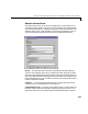
CAN 1- Baud rate — The third control (popup menu) lets you define the most
common baud rates for CAN port 1. If special timing is necessary (baud rate),
the value “User defined” can be selected. In this case the fourth control (edit
field) is used to provide the four values for the timing information. The vector
elements have the following meaning
[ Prescaler, Synchronisation-Jump-Width, Time-Segement-1,
Time-Segment-2 ]
For more information about these values see the Softing user manual for this
board.
CAN 2 - Physical bus — The fifth control (popup menu) is used to define the
physical CAN bus type of CAN port 2. In the board’s standard hardware
configuration only Highspeed CAN is supported. By extending the board with
Lowspeed CAN piggyback modules it is possible to additionally select
Lowspeed CAN as the physical bus. The value of this control shouldn’t be
changed to Lowspeed if no module is present for the corresponding CAN port.
If the module is present (see the Softing user manual on how to install the
modules) you can select between Highspeen and Lowspeed CAN here.
CAN 2 - Baud rate — The sixth control (popup menu) lets you define the most
common baud rates for CAN port 2. If special timing is necessary (baud rate),
the value “User defined” can be selected. In this case the seventh control (edit
field) is used to provide the four values for the timing information. The vector
elements have the following meaning
[ Prescaler, Synchronisation-Jump-Width, Time-Segement-1,
Time-Segment-2 ]
For more information about these values see the Softing user manual for this
board.
Initialization and Termination — The eighth and ninth control (edit fields)
can be used to define CAN messages sent during initialization and termination
of the Setup block.
PCI slot (-1: autosearch) — The tenth control (edit field) is used to define the
PCI slot in which the referenced board (board number) resides. If only one
board is present in the target system the value for this control should be –1