
Specifications


CAN driver blocks for the CAN-AC2 (ISA) with Intel 82527 CAN-Controller
4-19
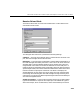
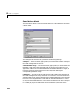
firmware’s dynamic object mode). The number of elements defined here, define
at the same time the number of inputs ports of the block. The block icon
displays the selected identifier at each input port. Each input port accepts the
data frame to be sent along with the CAN-message. The signal entering each
input port has to be a scalar of type double representing the maximum size of
8 bytes of a CAN-message’s data frame.
Data frame sizes — The fourth control (edit field) is used to define the data
frame size for each identifier (CAN-message) in bytes. It has to be a row vector
where the elements define a set of data frame sizes. Each element has to be in
the range between 1 and 8. If the data frame sizes for all identifiers defined in
the control above have to be the same, the size can be provided as a scalar only
and scalar expansion applies. If the sizes are different for at least two
identifiers (CAN-messages) one size element has to be provided for each
identifier defined in the control above. Therefore the length of the two vectors
have to be the same.
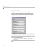
Show status: Output ports — The fourth control (checkbox) lets you enable
status output ports for each identifier (CAN message). If the checkbox is
checked, the block shows as many output ports as input ports. The data type of
each output port is a double and the value is identical to the return argument
of function CANPC_write_object(…) described in the Softing user manual.
Refer to the manual for more information.
Sample time — The fifth control (edit field) defines the sample time at which
the Send block is executed during a model (target application) run.
You can use as many instances of the Send block in the model as needed. For
example by using two instances of the block, different sample times at which
CAN messages are sent out can be defined. Or you can use multiple instances
to structure your model more efficiently.