
Specifications


4 CAN I/O Support
4-10
For more information about these values see the Softing user manual for this
board.
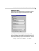
CAN 2 - Baud rate — The third control (popup menu) lets you define the most
common baud rates for CAN port 2. If special timing is necessary (baud rate),
the value “User defined” can be selected. In this case the fourth control (edit
field) is used to provide the four values for the timing information. The vector
elements have the following meaning
[ Prescaler, Synchronisation-Jump-Width, Time-Segement-1,
Time-Segment-2 ]
For more information about these values see the Softing user manual for this
board.
Initialization and Termination — The fifth and sixth control (edit fields) can
be used to define CAN messages sent during initialization and termination of
the Setup block.
Memory base address — The seventh control (popup menu) is used to define
the memory base address of the board. The address range used by the board
has to be set by hardware jumpers on the board itself. Refer to the Softing user
manual on how set the various address ranges. The setting in the dialog box
has to correspond to the jumper setting otherwise the board cannot be accessed.
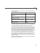
The available address ranges (memory base address) in the popup menu are
those supported by the board. Because the xPC Target kernel only reserves a
sub range (C0000 – DC000) of the 640 kilobyte to 1 megabyte address range for
memory mapped devices, the valid settings when used within a xPC target
systems are:
1 (16k): D0000-D3FFF
2 (16k): D4000-D7FFF
The board allows to activate proper termination for each of the two CAN ports
separately by means of hardware jumpers. Refer to the Softing user manual on
how the jumpers have to be set. Both CAN ports have to be terminated properly
when you use the provided loop-back model in order to test the board and
drivers.