
Operating instructions
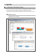
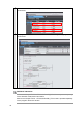
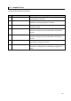


Table Of Contents
- Introduction
- Terms and Conditions Agreement
- Precautions
- Related Manuals
- Revision History
- 1. System to Construct and Configuration Devices
- 2. Before You Begin
- 3. Setting up the System
- 3.1. System Setup Procedures
- 3.2. Simulink PLC Coder & Sysmac Studio Operation Procedure
- 3.2.1. Outputting the Code using the Simulink PLC Coder
- 3.2.2. Importing the Code into the Sysmac Studio
- 3.2.3. Checking the Calculation Accuracy
- 3.2.4. Creating the EtherCAT Network Configuration
- 3.2.5. Setting the Axis
- 3.2.6. Creating Programs
- 3.2.7. Synchronization (Download)
- 3.2.8. System Operation Check
- 4. Appendix

35
4.1. Sample File List
The following sample files are related to this Guide.
We provide the sample files separately.
No.
File Name Description
1 PLCCoderDemoMC.mdl File that contains the Simulink model described in 2.2. Designing the
Control Algorithm of this Guide.
2 PLCCoderDemoMC.smc Sysmac Studio project file that contains Sysmac Studio programs
described in 3.2.6 Creating Programs of this Guide.
3 PLCCoderDemoMC_Torque.smc Sysmac Studio project file that contains the program to output torque
commands cyclically.
4 PLCCoderDemoMC_ADDA.mdl File that contains the Simulink model that shows the usage example of
GX-AD0471 Analog Input Terminal and GX-DA0271 Analog Output
Terminal.
5 PLCCoderDemoMC_ADDA.smc Sysmac Studio project file that shows the usage example of
GX-AD0471 Analog Input Terminal and GX-DA0271 Analog Output
Terminal.
6 PLCCoderDemoMC_LD.mdl File that contains the Simulink model described in 4.1. Programming in
Ladder Diagram Language of this Guide.
7 PLCCoderDemoMC_LD.smc Sysmac Studio project file that contains Sysmac Studio programs
described in 4.1. Programming in Ladder Diagram Language of this
Guide.