
Operating instructions
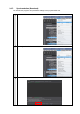
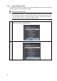
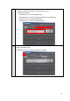
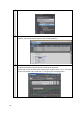
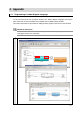
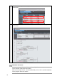


Table Of Contents
- Introduction
- Terms and Conditions Agreement
- Precautions
- Related Manuals
- Revision History
- 1. System to Construct and Configuration Devices
- 2. Before You Begin
- 3. Setting up the System
- 3.1. System Setup Procedures
- 3.2. Simulink PLC Coder & Sysmac Studio Operation Procedure
- 3.2.1. Outputting the Code using the Simulink PLC Coder
- 3.2.2. Importing the Code into the Sysmac Studio
- 3.2.3. Checking the Calculation Accuracy
- 3.2.4. Creating the EtherCAT Network Configuration
- 3.2.5. Setting the Axis
- 3.2.6. Creating Programs
- 3.2.7. Synchronization (Download)
- 3.2.8. System Operation Check
- 4. Appendix

2
When the code is imported to the Sysmac Studio, the BOOL variables are added as
shown below.
3
The program to call the function block is written in the ladder diagram language as
shown below.
Additional Information
Refer to the Sample File No. 6 PLCCoderDemoMC_LD.mdl that is provided separately
for the Simulink model used in this section.
Refer to the Sample File No. 7 PLCCoderDemoMC_LD.smc that is provided separately
for the program used in this section.
34