
Operating instructions
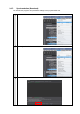
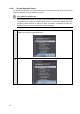
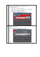
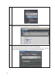
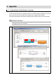
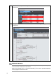


Table Of Contents
- Introduction
- Terms and Conditions Agreement
- Precautions
- Related Manuals
- Revision History
- 1. System to Construct and Configuration Devices
- 2. Before You Begin
- 3. Setting up the System
- 3.1. System Setup Procedures
- 3.2. Simulink PLC Coder & Sysmac Studio Operation Procedure
- 3.2.1. Outputting the Code using the Simulink PLC Coder
- 3.2.2. Importing the Code into the Sysmac Studio
- 3.2.3. Checking the Calculation Accuracy
- 3.2.4. Creating the EtherCAT Network Configuration
- 3.2.5. Setting the Axis
- 3.2.6. Creating Programs
- 3.2.7. Synchronization (Download)
- 3.2.8. System Operation Check
- 4. Appendix
4. Appendix
4.1. Programming in Ladder Diagram Language
To call a function block from a program written in the ladder diagram language, the function
block must have at least one BOOL input variable and one BOOL output variable.
This section describes the procedure for adding boolean signals to the block on the Simulink.
Additional Information
You also can add BOOL variables on the Sysmac Studio after importing the code without
changing the block on the Simulink.
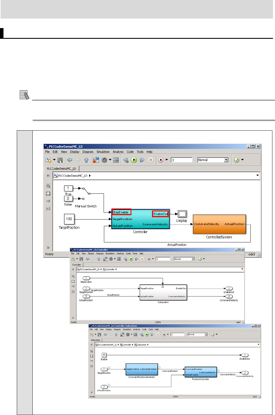
1
Add boolean signals to the Controller block on the Simulink.
33