
Operating instructions
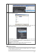
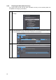
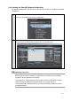
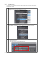
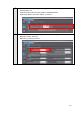
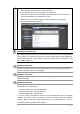
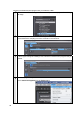
Table Of Contents
- Introduction
- Terms and Conditions Agreement
- Precautions
- Related Manuals
- Revision History
- 1. System to Construct and Configuration Devices
- 2. Before You Begin
- 3. Setting up the System
- 3.1. System Setup Procedures
- 3.2. Simulink PLC Coder & Sysmac Studio Operation Procedure
- 3.2.1. Outputting the Code using the Simulink PLC Coder
- 3.2.2. Importing the Code into the Sysmac Studio
- 3.2.3. Checking the Calculation Accuracy
- 3.2.4. Creating the EtherCAT Network Configuration
- 3.2.5. Setting the Axis
- 3.2.6. Creating Programs
- 3.2.7. Synchronization (Download)
- 3.2.8. System Operation Check
- 4. Appendix
3.2.5. Setting the Axis
You add an axis to control the Servo Drive, assign the Servo Drive to the axis, and make the
axis parameter settings.
1
Double-click Motion Control Setup in the Multiview Explorer and right-click Axis
Settings and select Add - Axis Settings from the menu.
2
Double-click MC_Axis000(0) (Axis 0) that was added under Motion Control Setup -
Axis Settings in the Multiview Explorer to display the axis parameter setting view.
3
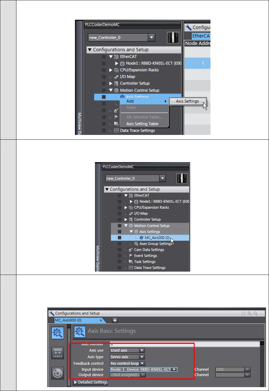
Make the Axis Basic Settings as shown below to assign the Servo Drive to the axis.
Axis type: Servo axis
Input device: Node: 1 Device: R88D-KN01L-ETC
24