
Operating instructions
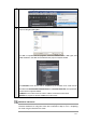
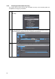
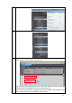
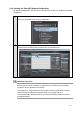
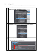
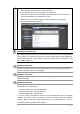
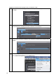
Table Of Contents
- Introduction
- Terms and Conditions Agreement
- Precautions
- Related Manuals
- Revision History
- 1. System to Construct and Configuration Devices
- 2. Before You Begin
- 3. Setting up the System
- 3.1. System Setup Procedures
- 3.2. Simulink PLC Coder & Sysmac Studio Operation Procedure
- 3.2.1. Outputting the Code using the Simulink PLC Coder
- 3.2.2. Importing the Code into the Sysmac Studio
- 3.2.3. Checking the Calculation Accuracy
- 3.2.4. Creating the EtherCAT Network Configuration
- 3.2.5. Setting the Axis
- 3.2.6. Creating Programs
- 3.2.7. Synchronization (Download)
- 3.2.8. System Operation Check
- 4. Appendix
3.2.4. Creating the EtherCAT Network Configuration
You register a R88D-KN01L-ECT Servo Drive that operates as axis 0 on the EtherCAT network
configuration.
1
Double-click EtherCAT in the Multiview Explorer to display the EtherCAT Tab Page
where you edit the EtherCAT network configuration.
2
Drag the R88D-KN01L-ECT from the Toolbox to the master.
The Servo Drive is added under the master with a node address of 1.
Additional Information
To use digital I/O devices, analog I/O devices, and encoder input devices, add the
devices using the same procedure. For data access to the devices that you added,
register the device variables in the I/O Map.
The examples for using GX-AD0471 Analog Input Terminal and GX-DA0271 Analog
Output Terminal are provided as samples. Refer to the Sample File No. 4
PLCCoderDemoMC_ADDA.mdl and No. 5 PLCCoderDemoMC_ADDA.smc that are
provided separately.
23