
Operating instructions
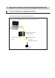
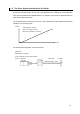
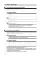
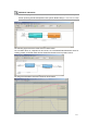
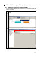
Table Of Contents
- Introduction
- Terms and Conditions Agreement
- Precautions
- Related Manuals
- Revision History
- 1. System to Construct and Configuration Devices
- 2. Before You Begin
- 3. Setting up the System
- 3.1. System Setup Procedures
- 3.2. Simulink PLC Coder & Sysmac Studio Operation Procedure
- 3.2.1. Outputting the Code using the Simulink PLC Coder
- 3.2.2. Importing the Code into the Sysmac Studio
- 3.2.3. Checking the Calculation Accuracy
- 3.2.4. Creating the EtherCAT Network Configuration
- 3.2.5. Setting the Axis
- 3.2.6. Creating Programs
- 3.2.7. Synchronization (Download)
- 3.2.8. System Operation Check
- 4. Appendix
2. Before You Begin
2.1. Wiring the Devices and Installing the Software
You wire the devices and install the software on the computer as described in 1.1. System
Configuration and Configuration Devices.
Additional Information
Refer to the manuals for the devices that are used in the system for wiring of the
devices.
Additional Information
Refer to the Sysmac Studio Version 1 Operation Manual (Cat. No. W504) for installation
of the Sysmac Studio.
Additional Information
Access the website of The MathWorks Inc. or refer to the MATLAB & Simulink
Installation Guide that is provided by The MathWorks Inc. for installation of
MATLAB/Simulink and Simulink PLC Coder.
2.2. Designing the Control Algorithm
You build a model for the Controller and controlled system using the Simulink. The code is
created for the Controller by the Simulink PLC Coder. Therefore, you need to build the model
using a block supported by the Simulink PLC Coder.
Additional Information
Access the website of The MathWorks Inc. or refer to the Simulink User Guide that is
provided by The MathWorks Inc. for how to use the Simulink.
Additional Information
Access the website of The MathWorks Inc. or refer to the Simulink PLC Coder User’s
Guide that is provided by The MathWorks Inc. for the blocks supported by the Simulink
PLC Coder.
This Guide gives an example for designing the control algorithm so that an NJ-series CPU Unit
controls the position and a Servo Drive controls the velocity.
In the Sample File No. 1 PLCCoderDemoMC.mdl that is provided separately, a model is
created for the Controller (Controller block) and controlled system (ControlledSystem block) by
the Simulink as shown in the following figure.
The sampling time of the Controller is set to 1 ms in the sample.
12