
Operating instructions
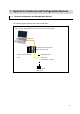
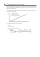
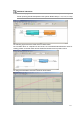
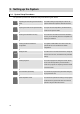
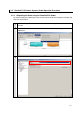
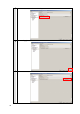
Table Of Contents
- Introduction
- Terms and Conditions Agreement
- Precautions
- Related Manuals
- Revision History
- 1. System to Construct and Configuration Devices
- 2. Before You Begin
- 3. Setting up the System
- 3.1. System Setup Procedures
- 3.2. Simulink PLC Coder & Sysmac Studio Operation Procedure
- 3.2.1. Outputting the Code using the Simulink PLC Coder
- 3.2.2. Importing the Code into the Sysmac Studio
- 3.2.3. Checking the Calculation Accuracy
- 3.2.4. Creating the EtherCAT Network Configuration
- 3.2.5. Setting the Axis
- 3.2.6. Creating Programs
- 3.2.7. Synchronization (Download)
- 3.2.8. System Operation Check
- 4. Appendix
1.2. The Servo System Constructed in this Guide
This guide describes the procedure to start up the system for single-axis positioning with a
Servo Drive and Servomotor for one axis. The operations from creating the control algorithm
using the Simulink® from the MathWorks® Inc. to operation check using the actual devices are
given as the startup procedure.
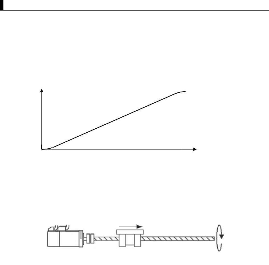
The single-axis Servo system that is set up in this Guide performs the single-axis positioning
operation on the following path.
The mechanical configuration is as shown below.
Time
Position
Travel distance: 100 mm
Maximum velocity: 50 mm/s
Maximum acceleration: 185 mm/s
2
Servomotor
Rated sp
eed: 3,000 r/min
Ball scre
w pitch: 10 mm
Ball screw
10 mm
Command pulse count per motor rotation:
20 bits = 1,048,576
1 rotation
11