
Operating instructions
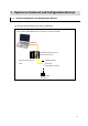
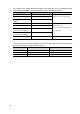
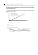
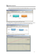
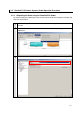
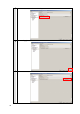
Table Of Contents
- Introduction
- Terms and Conditions Agreement
- Precautions
- Related Manuals
- Revision History
- 1. System to Construct and Configuration Devices
- 2. Before You Begin
- 3. Setting up the System
- 3.1. System Setup Procedures
- 3.2. Simulink PLC Coder & Sysmac Studio Operation Procedure
- 3.2.1. Outputting the Code using the Simulink PLC Coder
- 3.2.2. Importing the Code into the Sysmac Studio
- 3.2.3. Checking the Calculation Accuracy
- 3.2.4. Creating the EtherCAT Network Configuration
- 3.2.5. Setting the Axis
- 3.2.6. Creating Programs
- 3.2.7. Synchronization (Download)
- 3.2.8. System Operation Check
- 4. Appendix

10
The models of the devices that are described in this Guide are given in the following table.
When selecting devices for an actual application, refer to the device manuals.
Device name Model Manual name
NJ-series CPU Unit NJ301-1200 (Unit version 1.04)
NJ-series Power Supply Unit NJ-PA3001
EtherCAT communications
cables
XS5W-T421-CMD-K
NJ-series CPU Unit Hardware
User’s Manual (Cat. No. W500)
AC Servo Drives R88D-KN01L-ECT (version 2.10)
AC Servomotors R88M-K10030L
Motor Power Cables
(for the AC Servo Drives)
R88A-CAKA003S
Encoder Cables
(for the AC Servo Drives)
R88A-CRKA003C
AC Servomotors/Servo Drives
(Built-in EtherCAT
Communications) User's Manual
(Cat. No. I576)
USB cable Commercially available USB cable
*1
---
*1. Use a USB2.0 (or 1.1) cable (A connector - B connector), 5.0 m max.
The names and versions of the software that are used in this Guide are given below. Install the
following software to a computer (OS: Windows 7).
Manufacturer Name Version
OMRON Corporation Sysmac Studio Version 1.05
The MathWorks Inc. MATLAB/Simulink R2013a
The MathWorks Inc. Simulink PLC Coder R2013a