
Operating instructions
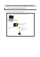
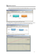
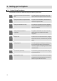
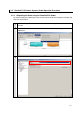
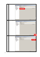
Table Of Contents
- Introduction
- Terms and Conditions Agreement
- Precautions
- Related Manuals
- Revision History
- 1. System to Construct and Configuration Devices
- 2. Before You Begin
- 3. Setting up the System
- 3.1. System Setup Procedures
- 3.2. Simulink PLC Coder & Sysmac Studio Operation Procedure
- 3.2.1. Outputting the Code using the Simulink PLC Coder
- 3.2.2. Importing the Code into the Sysmac Studio
- 3.2.3. Checking the Calculation Accuracy
- 3.2.4. Creating the EtherCAT Network Configuration
- 3.2.5. Setting the Axis
- 3.2.6. Creating Programs
- 3.2.7. Synchronization (Download)
- 3.2.8. System Operation Check
- 4. Appendix
1. System to Construct and Configuration Devices
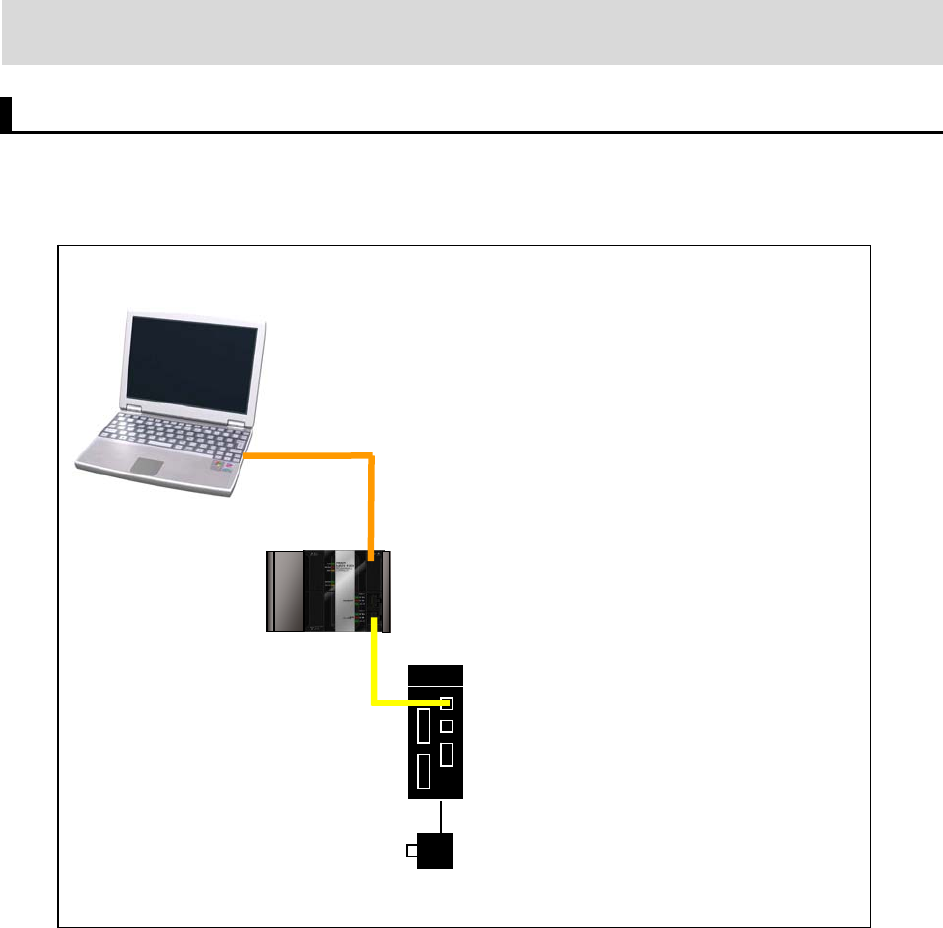
1.1. System Configuration and Configuration Devices
This section describes the system configuration and configuration devices used in this Guide.
The following figure represents the system configuration.
Comp
uter
Sysmac Studio, MATLAB/Simulink, and Simulink PLC Coder are installed.
USB cable
NJ-PA3001 Power Supply Unit
9
EtherCA
T communications
cable
R88D-KN01L-ECT
Servo Drive
Node Address 1 (Axis 0)
R88M-K10030T
NJ301-1200 CPU Unit
Servomotor