Machine Automation Controller NJ-series Startup Guide for Simulink ® PLC Coder™ & Sysmac Studio SYSMAC-SE20□□ NJ501-□□□□ NJ301-□□□□ R88D-KN□-ECT GX-AD0471/DA0271 W529-E1-01
©OMRON, 2013 All rights reserved. No part of this publication may be reproduced, stored in a retrieval system, or transmitted, in any form, or by any means, mechanical, electronic, photocopying, recording, or otherwise, without the prior written permission of OMRON. No patent liability is assumed with respect to the use of the information contained herein.
Introduction The NJ-series Startup Guide for Simulink® PLC Coder™ and Sysmac Studio (hereinafter, may be referred to as “this Guide”) describes the startup procedures that are required to use a combination of Simulink® PLC Coder™ from The MathWorks® Inc. and NJ-series CPU Unit for the first time and the basic operating instructions for the Sysmac Studio. A simple single-axis positioning example is used for the discussion.
Terms and Conditions Agreement Read and understand this catalog. Please read and understand this catalog before purchasing the products. Please consult your OMRON representative if you have any questions or comments. Warranties. (a) Exclusive Warranty. Omron’s exclusive warranty is that the Products will be free from defects in materials and workmanship for a period of twelve months from the date of sale by Omron (or such other period expressed in writing by Omron).
and limitations of use which apply to the Product. This information by itself is not sufficient for a complete determination of the suitability of the Product in combination with the end product, machine, system, or other application or use. Buyer shall be solely responsible for determining appropriateness of the particular Product with respect to Buyer’s application, product or system. Buyer shall take application responsibility in all cases.
Precautions • When building a system, check the specifications for all devices and equipment that will make up the system and make sure that the OMRON products are used well within their rated specifications and performances. Safety measures, such as safety circuits, must be implemented in order to minimize the risks in the event of a malfunction. • Thoroughly read and understand the manuals for all devices and equipment that will make up the system to ensure that the system is used safely.
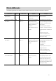
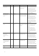
Related Manuals The following manuals are related to the NJ-series Controllers. Use these manuals for reference. Manual name Sysmac Studio Version 1 Cat. No. W504 Model numbers SYSMAC-SE2□□□ Operation Manual Application Description Learning about the operating The operating procedures of the Sysmac procedures and functions of the Studio are described. Sysmac Studio.
Manual name NJ-series Instructions Cat. No. W502 Reference Manual Model numbers Application Description NJ501-□□□□ Learning detailed specifications The instructions in the instruction set NJ301-□□□□ on the basic instructions of an (IEC61131-3 specifications) are described. NJ-series CPU Unit. When programming, use this manual together with the NJ-series CPU Unit Hardware User’s Manual (Cat. No. W500) and NJ-series CPU Unit Software User’s Manual (Cat. No. W501).
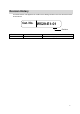
Revision History A manual revision code appears as a suffix to the catalog number on the front and back covers of the manual. Cat. No.
CONTENTS Introduction............................................................................................................... 1 Intended Audience .................................................................................................. 1 Applicable Products ................................................................................................ 1 Special Information .................................................................................................
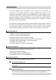
1. System to Construct and Configuration Devices 1.1. System Configuration and Configuration Devices This section describes the system configuration and configuration devices used in this Guide. The following figure represents the system configuration. Computer Sysmac Studio, MATLAB/Simulink, and Simulink PLC Coder are installed.
The models of the devices that are described in this Guide are given in the following table. When selecting devices for an actual application, refer to the device manuals. Device name Model Manual name NJ-series CPU Unit NJ301-1200 (Unit version 1.04) NJ-series CPU Unit Hardware NJ-series Power Supply Unit NJ-PA3001 User’s Manual (Cat. No. W500) EtherCAT communications XS5W-T421-CMD-K cables AC Servo Drives R88D-KN01L-ECT (version 2.
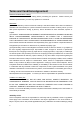
1.2. The Servo System Constructed in this Guide This guide describes the procedure to start up the system for single-axis positioning with a Servo Drive and Servomotor for one axis. The operations from creating the control algorithm using the Simulink® from the MathWorks® Inc. to operation check using the actual devices are given as the startup procedure. The single-axis Servo system that is set up in this Guide performs the single-axis positioning operation on the following path.
2. Before You Begin 2.1. Wiring the Devices and Installing the Software You wire the devices and install the software on the computer as described in 1.1. System Configuration and Configuration Devices. Additional Information Refer to the manuals for the devices that are used in the system for wiring of the devices. Additional Information Refer to the Sysmac Studio Version 1 Operation Manual (Cat. No. W504) for installation of the Sysmac Studio.
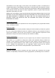
Additional Information Set the sampling time of the Controller so that it matches the task period of the Sysmac Studio. (Primary periodic task period on the Sysmac Studio: 500 μs, 1 ms, 2 ms, or 4 ms) The following figure shows the inside of the Controller block. The Controller block is composed of two blocks; the CommandPositionGenerator block for creating position command values and the PositionController block for position control. You will get the simulation execution results as shown below.
3. Setting up the System 3.1. System Setup Procedures The operation procedure of Simulink and Sysmac Studio is given below. 3.2.1 Outputting the Code using the Simulink PLC You make a setting for outputting the code for the Coder Sysmac Studio and output the code with test code. ▼ 3.2.2 Importing the Code into the Sysmac Studio You import the code outputted by the Simulink PLC Coder into the Sysmac Studio. ▼ 3.2.
3.2. Simulink PLC Coder & Sysmac Studio Operation Procedure 3.2.1. Outputting the Code using the Simulink PLC Coder You make a setting for outputting the code for the Sysmac Studio and output the code with test code from the Simulink. 1 Open the Sample File No. 1 PLCCoderDemoMC.mdl that is provided separately on the Simulink. 2 Click the Controller block to output the code and select PLC Code - Options from the Code Menu.
16 4 Select the Generate testbench for subsystem check box. 5 Click the Apply Button. 6 Click the Generate Code Button.
7 The PLCCoderDemoMC.xml file is saved into the plcsrc folder specified in Code Output Directory. Additional Information When you adjust the parameters after code generation, you generate the code as a variable, not a constant (literal). Access the website of The MathWorks Inc. or refer to the Simulink PLC Coder User’s Guide that is provided by The MathWorks Inc. for the setting procedure.
3.2.2. Importing the Code into the Sysmac Studio You import the code outputted by the Simulink PLC Coder into the Sysmac Studio. Additional Information Refer to the Sysmac Studio Version 1 Operation Manual (Cat. No. W504) for how to use the Sysmac Studio. 1 Start the Sysmac Studio and create a new project. Set the Select Device Area as shown below. Category: Controller Device: NJ301-1200 Version: 1.
3 Select Import ST Program from the Tools Menu. 4 Select the PLCCoderDemoMC.xml file that was outputted in the previous section in the Import ST Program Dialog Box. The data is imported and the programs, functions, function blocks, data types, and global variables in the XML file are added to the project of Sysmac Studio.
3.2.3. Checking the Calculation Accuracy You confirm that the code has the same calculation accuracy as the Simulink (within the acceptable error range) by a simulation. 1 Double-click the Task Settings in the Multiview Explorer to display the Task Settings Tab Page. 2 Set the task period to 1 ms in the Task Settings View on the Sysmac Studio so that the period matches the sampling time of the Controller on the Simulink. 3 20 Select the MainTB program in the Program Assignment Settings View.
4 Select Run from the Simulation Menu of the Sysmac Studio. 5 Double-click TestBench in the Multiview Explorer to display the program. 6 Confirm that testVerify is True and testCycleNum is the value of TEST_CYCLE_COUNT written in the comment. You can confirm that calculation accuracy of the output data is the same level as the Simulink (within the acceptable error range) if testVerify is True.
Additional Information The initial value of the acceptable error depends on the data type as shown below. Set an appropriate value according to the actual application. ■ Integer data: 0 (Match) ■ REAL data: 0.0001 ■ LREAL data: 1.
3.2.4. Creating the EtherCAT Network Configuration You register a R88D-KN01L-ECT Servo Drive that operates as axis 0 on the EtherCAT network configuration. 1 Double-click EtherCAT in the Multiview Explorer to display the EtherCAT Tab Page where you edit the EtherCAT network configuration. 2 Drag the R88D-KN01L-ECT from the Toolbox to the master. The Servo Drive is added under the master with a node address of 1.
3.2.5. Setting the Axis You add an axis to control the Servo Drive, assign the Servo Drive to the axis, and make the axis parameter settings. 1 Double-click Motion Control Setup in the Multiview Explorer and right-click Axis Settings and select Add - Axis Settings from the menu. 2 Double-click MC_Axis000(0) (Axis 0) that was added under Motion Control Setup Axis Settings in the Multiview Explorer to display the axis parameter setting view.
4 Make the Unit Conversion Settings according to the mechanical configuration. Unit of display: mm Command pulse count per motor rotation: 1048576 pulse/rev Work travel distance per motor rotation: 10 mm/rev 5 Make the Operation Settings according to the mechanical configuration.
3.2.6. Creating Programs You create a program for calling the function blocks whose code was outputted by the Simulink PLC Coder and a program for outputting command values to the Servo Drive. 1 Delete TestBench and MainTB because they are used for the test to check the calculation accuracy. Right-click TestBench in the Multiview Explorer and select Delete from the menu. Right-click MainTB in the Multiview Explorer and select Delete from the menu.
2 Create the PositionControl program for the following processing.
Assigning the PositionControl program that you created to a task. 3 Double-click the Task Settings in the Multiview Explorer to display the Task Settings Tab Page. 4 Set the task period to 1ms in the Task Settings View on the Sysmac Studio so that the period matches the sampling time of the Controller on the Simulink. 5 In the Program Assignment Settings View, select the PositionControl program that you created. 6 Check the program that you created. Select Check All Programs from the Project Menu.
3.2.7. Synchronization (Download) You transfer the programs and parameter settings to the physical CPU Unit. 1 Select Online from the Controller Menu. 2 Select Synchronization from the Controller Menu. 3 Click the Transfer to Controller Button.
3.2.8. System Operation Check You execute the operation according to the programs transferred to the physical CPU Unit and check the operation using the data trace function. Precautions for Correct Use The physical motor will run. Thoroughly read and understand the manuals for all devices that make up the system to ensure that the system is used safely.
3 Make the trace settings as shown below. Trigger condition: Rising edge of PositionControl.Smv_Ex Trace target variables: PositionControl.i_Controller.TargetPosition PositionControl.i_Controller.i0_PositionController.CommandPosition PositionControl.i_Controller.ActualPosition PositionControl.i_Controller.CommandVelocity 4 Click the Start Trace Button (with red filled circle icon) on the upper left part of the window to start data tracing. The data trace function is started and waits for the trigger.
5 Double-click PositionControl in the Multiview Explorer to display the program. 6 Change the value of StartPg variable for execution conditions of Servo ON, home definition, and command value output to True to start positioning. 7 When you click the Stop Button (with write square icon) or the trace data becomes full, the data trace operation will stop and the results will be displayed. Confirm that you got the same trace results as the waveform shown in 1.2.
4. Appendix 4.1. Programming in Ladder Diagram Language To call a function block from a program written in the ladder diagram language, the function block must have at least one BOOL input variable and one BOOL output variable. This section describes the procedure for adding boolean signals to the block on the Simulink. Additional Information You also can add BOOL variables on the Sysmac Studio after importing the code without changing the block on the Simulink.
2 When the code is imported to the Sysmac Studio, the BOOL variables are added as shown below. 3 The program to call the function block is written in the ladder diagram language as shown below. Additional Information Refer to the Sample File No. 6 PLCCoderDemoMC_LD.mdl that is provided separately for the Simulink model used in this section. Refer to the Sample File No. 7 PLCCoderDemoMC_LD.smc that is provided separately for the program used in this section.
4.1. Sample File List The following sample files are related to this Guide. We provide the sample files separately. No. 1 File Name PLCCoderDemoMC.mdl Description File that contains the Simulink model described in 2.2. Designing the Control Algorithm of this Guide. 2 PLCCoderDemoMC.smc Sysmac Studio project file that contains Sysmac Studio programs described in 3.2.6 Creating Programs of this Guide. 3 PLCCoderDemoMC_Torque.
Terms and Conditions of Sale 1. Offer; Acceptance. These terms and conditions (these "Terms") are deemed part of all quotes, agreements, purchase orders, acknowledgments, price lists, catalogs, manuals, brochures and other documents, whether electronic or in writing, relating to the sale of products or services (collectively, the "Products") by Omron Electronics LLC and its subsidiary companies (“Omron”).
OMRON INDUSTRIAL AUTOMATION • THE AMERICAS HEADQUARTERS Schaumburg, IL USA • 847.843.7900 • 800.556.6766 • www.omron247.com OMRON CANADA, INC. • HEAD OFFICE Toronto, ON, Canada • 416.286.6465 • 866.986.6766 • www.omron247.com OMRON ARGENTINA • SALES OFFICE Cono Sur • 54.11.4783.5300 OMRON ELECTRONICS DE MEXICO • HEAD OFFICE México DF • 52.55.59.01.43.00 • 001.800.556.6766 • mela@omron.com OMRON CHILE • SALES OFFICE Santiago • 56.9.9917.3920 OMRON ELECTRONICS DE MEXICO • SALES OFFICE Apodaca, N.L. • 52.