
User guide

26 www.xilinx.com System Generator for DSP Getting Started Guide
UG639 (v 14.3) October 16, 2012
Chapter 4: Getting Started
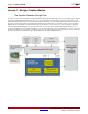
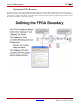
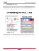
Defining the FPGA Boundary
System Generator works with standard Simulink models. Two blocks called “Gateway In” and “Gateway Out”
define the boundary of the FPGA from the Simulink simulation model. The Gateway In block converts the floating
point input to a fixed-point number. You double-click on the block to bring up the properties editor which is where
the fixed-point number can be fully specified.