
User`s guide

Constructing Signals
3-51
To build the model, define the following variable in the MATLAB workspace.
A = [1 1 5 -1;2 1 5 -2;3 0 5 -3;405-4;515-5;615-6];
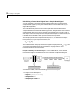
Connect the Buffer block to a Signal From Workspace source and a To
Workspace sink with the following parameter settings:
•In the Signal From Workspace block, set:
-
Signal = A
- Sample time = 1
- Samples per frame = 1
•In the Buffer block, set:
-
Output buffer size (per channel) = 3
- Buffer overlap = 1
- Initial conditions = 0
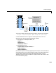
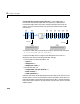
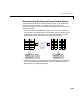
Note that the inputs do not begin appearing at the output until the second row
of the second matrix. This is due to the block’s latency. See “Delay and Latency”
on page 3-85 for general information about algorithmic delay, and see
“Buffering Delay and Initial Conditions” on page 3-53 for instructions on how
to calculate buffering delay.
405 4–
515 5–
615 6–
615 6–
t=0
t=2
t=5
t=4
t=3
t=1
first
frame-based
output
T
si
= 1
515 5–
305 3–
405 4–
215 2–
115 1–
(M
o
=3, L=1)
0000
115 1–
215 2–
0000
0000
0000
215 2–
305 3–
405 4–
first sample-based
input
t=0t=4t=6 t=2
ch4
ch3
ch1
ch2
ch4
ch3
ch2
ch1
Sample-based input,
sample period = T
si
Frame-based output,
frame period = (M
o
-L)∗T
si
ch4
ch3
ch2
ch1
ch4
ch3
ch2
ch1