
User`s guide

Sample Rates and Frame Rates
3-17
where M
i
and M
o
are the input and output frame sizes, respectively.
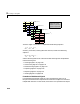
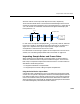
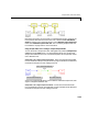
The illustration below shows a one-channel frame-based signal with a frame
size (M
i
) of 4 and a frame period (T
fi
) of 1. The sample period, T
si
, is therefore 1/
4, or 0.25 seconds. A Probe block connected to this signal would display the
frame period T
fi
=1.
In most cases, the sequence sample period T
si
is of primary interest, while the
frame rate is simply a consequence of the frame size that you choose for the
signal. For a sequence with a given sample period, a larger frame size
corresponds to a slower frame rate, and vice versa.
For information on converting a signal from one sample rate or frame rate to
another, see “Converting Sample Rates and Frame Rates” on page 3-20.
Inspecting Sample Rates and Frame Rates
When constructing a frame-based or multirate model, it is often helpful to
check the rates that Simulink computes for different signals. There are two
basic ways to inspect the sample rates and frame rates in a model. These are
described in the following sections:
•“Using the Probe Block to Inspect Rates”
•“Using Sample Time Color Coding to Inspect Sample Rates”
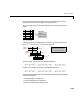
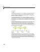
Using the Probe Block to Inspect Rates
Connect Simulink’s Probe block to any line to display the period of the signal
on that line. The period is displayed in the block icon itself (together with the
line width and data type, if desired), making it easy to verify that the sample
rates in the model are what you expect them to be. When the line width and
data type displays are suppressed (by deselecting the appropriate check boxes
in the block dialog box), the Probe block looks like this.
13
14
15
16
9
10
11
12
5
6
7
8
1
2
3
4
t=0t=1t=2t=3
first input frame
T
fi
= 1
T
si
= 0.25