
User`s guide

N-Sample Switch
5-327
5N-Sample Switch
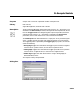
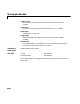
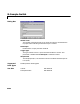
Purpose Switch between two inputs after a specified number of sample periods.
Library Signal Management / Switches and Counters
Description The N-Sample Switch block outputs the signal connected to the top input port
during the first N sample times after the simulation begins or the block is reset,
where N is specified by the
Switch count value. Beginning with output sample
N+1, the block outputs the signal connected to the bottom input until the next
reset event or the end of the simulation.
The sample period of the output is specified by the
Sample time parameter
(i.e., the output sample period is not inherited from the sample period of either
input). The block applies a zero-order hold at the input ports, so the value the
block reads from a given port between input sample times is the value of the
most recent input to that port.
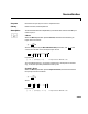
Both inputs must have the same dimension, except in the following two cases:
•When one input is a scalar, the block expands the scalar input to match the
size of the other input.
•When one input is a 1-D vector and the other input is a row or column vector
with the same number of elements, the block reshapes the 1-D vector to
match the dimension of the other input.
The inputs must either both be frame-based or both be sample-based.
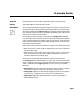
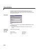
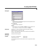
The
Reset input check box enables the Rst input port. At any time during the
count, a trigger event at the
Rst port resets the counter to zero. The triggering
event is specified by the
Trigger type pop-up menu, and can be one of the
following:
•
Rising edge triggers the reset when the trigger input rises from a negative
value to zero or a positive value, or from zero to a positive value.
•
Falling edge triggers the reset when the trigger input falls from a positive
value to zero or a negative value, or from zero to a negative value.
•
Either edge triggers the reset when either a rising or falling edge (as
described above) occurs.