
User`s guide


Multiphase Clock
5-320
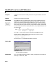
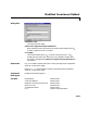
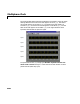
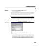
The Scope window below shows the Multiphase Clock block’s output for these
settings. Note that the first active level appears at t=0 on
y(3), the second
active level appears at t=0.002 on
y(4), the third active level appears at
t=0.004 on
y(5), the fourth active level appears at t=0.006 on y(1), and the
fifth active level appears at t=0.008 on
y(2). Each signal becomes active
1/(5
∗100) seconds after the previous signal.
To experiment further, try changing the
Number of phase intervals over
which clock is active
setting to 3 so that the active-level duration is three
phase intervals (60% duty cycle).
Signal 1
Signal 2
Signal 3
Signal 4
Signal 5