
User`s guide

Multiphase Clock
5-319
5Multiphase Clock
Purpose Generate multiple binary clock signals.
Library Signal Management / Switches and Counters
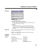
Description The Multiphase Clock block generates a sample-based 1-by-N vector of clock
signals, where the integer N is specified by the
Number of phases parameter.
Each of the N phases has the same frequency, f, specified in hertz by the
Clock
frequency
parameter.
The clock signal indexed by the
Starting phase parameter is the first to
become active, at t=0. The other signals in the output vector become active in
turn, each one lagging the preceding signal’s activation by 1/(N
∗f) seconds, the
phase interval. The period of the sample-based output is therefore 1/(N
∗f)
seconds.
The active level can be either high (
1) or low (0), as specified by the Active level
(polarity)
parameter. The duration of the active level, D, is set by the Number
of phase intervals over which the clock is active
. This value, which can be
an integer value between 1 and N-1, specifies the number of phase intervals
that each signal should remain in the active state after becoming active. The
active duty cycle of the signal is D/N.
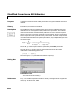
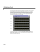
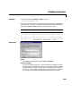
Example Configure the Multiphase Clock block in the model below to generate a 100 Hz
five-phase output in which the third signal is first to become active. Use a high
active level with a duration of one interval.
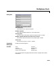
The corresponding settings are as follows:
•
Clock frequency = 100
•Number of phases = 5
•Starting phase = 3
•Number of phase intervals over which the clock is active = 1
•Active level (polarity) = High (1)