
User`s guide


FIR Interpolation
5-204
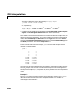
The filter coefficient vector generated by fir1(3,0.25) is
[0.0386 0.4614 0.4614 0.0386]
or, equivalently,
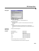
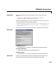
•Configure the Probe blocks by deselecting the
Probe width, Probe complex
signal
, and Probe signal dimensions check boxes (if desired).
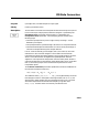
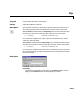
This model is multirate because there are at least two distinct sample rates, as
shown by the two Probe blocks. To run this model in Simulink’s multitasking
mode, select
Fixed-step and discrete from the Type controls in the Solver
panel of the
Simulation Parameters dialog box, and select MultiTasking from
the
Mode parameter. Also set the Stop time to 30.
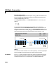
Run the model and look at the output,
yout. The first few samples of each
channel are shown below.
yout =
0 0
0 0
0 0
0 0
0.0386 -0.0386
0.4614 -0.4614
0.5386 -0.5386
0.9614 -0.9614
1.0386 -1.0386
Since we ran this frame-based multirate model in multitasking mode, the first
four (M
i
) output rows are zero. The first filtered input matrix row appears in
the output as sample 5 (i.e., sample M
i
+1). Every second row is an interpolated
value.
Example 2
The dspintrp demo provides another simple example, and the dspmrf_menu
demo illustrates the use of the FIR Interpolation block in a number of
multistage multirate filters.
Hz() Bz() 0.0386 0.04614z
1–
0.04614z
2–
0.0386z
3–
+++==