
User`s guide

FIR Interpolation
5-203
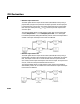
input matrix) appears in the output as sample M
i
+1, followed by L-1
interpolated values, the second filtered input sample, and so on. See the
example below for an illustration of this case.
See “Excess Algorithmic Delay (Tasking Latency)” on page 3-91 and “The
Simulation Parameters Dialog Box” in the Simulink documentation for more
information about block rates and Simulink’s tasking modes.
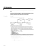
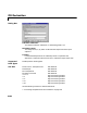
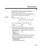
Example Example 1
Construct the frame-based model shown below.
Adjust the block parameters as follows.
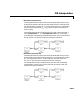
•Configure the Signal From Workspace block to generate a two-channel
signal with frame size of 4 and sample period of 0.25. This represents an
output frame period of 1 (0.25
∗4). The first channel should contain the
positive ramp signal 1, 2, ..., 100, and the second channel should contain the
negative ramp signal -1, -2, ..., -100.
-
Signal = [(1:100)' (-1:-1:-100)']
- Sample time = 0.25
- Samples per frame = 4
•Configure the FIR Interpolation block to interpolate the two-channel input
by increasing the output frame rate by a factor of 2 relative to the input
frame rate. Use a third-order filter (m=3) with normalized cutoff
frequency, f
n0
, of 0.25. (Note that f
n0
and m satisfy f
n0
≤ 1/L and m >L.)
-
FIR filter coefficients = fir1(3,0.25)
- Interpolation factor = 2
- Framing = Maintain input frame size