
User`s guide

FFT
5-176
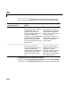
Ordering Output Column Entries (Output in bit-reversed order Parameter)
Set the Output in bit-reversed order parameter as follows to indicate the
ordering of the output’s column elements. For a definition of bit-reversed
ordering, see “Description of Bit-Reversed Ordering” on page 5-177.
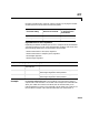
Note Linearly ordering the output requires extra data sorting manipulation,
so in some situations it may be better to output in bit-reversed order as
illustrated in the example, “Use of Outputs in Bit-Reversed Order” on
page 5-179.
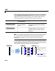
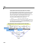
The next diagram illustrates the difference between linear and bit-reversed
outputs. Note that output values in linear and bit-reversed order are the same;
only the order in which they appear in the columns differs.
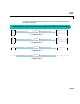
Parameter Setting Ordering of Output
Channel Elements
Output Column Entries
Linear order
(See the following
note.)
kth column element is the DFT of the
corresponding input column at the kth
frequency.
Bit-reversed order kth column element is the DFT of the
corresponding input column at the rth
frequency, where r is the bit reversed
value of k.
1
2
3
4
5
6
7
8
36
4– 9.7i+
4– 4i+
4– 1.7i+
4–
4– 1.7i–
4– 4i–
4– 9.7i–
36
4–
4– 4i+
4– 4i–
4– 9.7i+
4– 1.7i–
4– 1.7i+
4– 9.7i–
w
1
w
2
w
3
w
4
w
5
w
6
w
7
w
0
Output in
bit-reversed order
Output in
linear order
Output can
be ordered
in two ways
w
k
is the
k
th frequency at which
the block computes the FFT. For an
N
-point FFT,
w
k
=2π
k/N k=0,1,...,N-1
w
4
w
2
w
6
w
1
w
5
w
3
w
7
w
0
Bit reverse the
frequency indices
and indicate the
frequencies at which the block
computes the FFT to get the output
Input must be
in linear order