
User`s guide

Dyadic Analysis Filter Bank
5-151
5Dyadic Analysis Filter Bank
Purpose Decompose a signal into components of equal or logarithmically decreasing
frequency intervals and sample rates.
Library Filtering / Multirate Filters
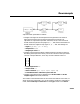
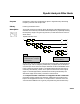
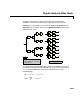
Description The Dyadic Analysis Filter Bank block decomposes a broadband signal into a
collection of successively more bandlimited components by repeatedly dividing
the frequency range. The typical (asymmetric) n-level filter bank structure is
shown below.
At each level, the low-frequency output of the previous level is decomposed into
adjacent high- and low-frequency subbands by a highpass (HP) and lowpass
(LP) filter pair. Each of the two output subbands is half the bandwidth of the
input to that level (hence “dyadic”). The bandlimited output of each filter is
maximally decimated by a factor of 2 to preserve the bit rate of the original
signal. In wavelet applications (see below) the aliasing introduced by the
decimation stage can be exactly canceled in reconstruction.
The
Lowpass FIR filter coefficients and Highpass FIR filter coefficients
parameters specify (respectively) the filter coefficients to be used for every
lowpass and highpass direct-form II transpose filter in the filter bank. The
values of these coefficients are typically computed using the wavelet family
HP
LP
↓2
↓2
HP
↓2
LP
↓2
HP
↓2
LP
↓2
u
HP: highpass filter with f
c
≈ 1/2 Nyquist
LP: lowpass filter with
f
c
≈ 1/2 Nyquist
↓2: downsample by 2
y
1
y
2
y
3
y
n
HP
↓2
LP
↓2
. . .
y
n
+1
Asymmetric Fi
l
ter Ban
k
, n Leve
l
s
2T
s
4T
s
8T
s
T
so
=(2
k
)T
s
for output y
k
, 1 ≤ k ≤ n
T
so
=(2
n
)T
s
for output y
n
+1
T
si
=T
s