
User`s guide

Counter
5-104
5Counter
Purpose Count up or down through a specified range of numbers.
Library Signal Management / Switches and Counters
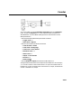
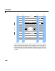
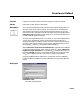
Description The Counter block increments or decrements an internal counter each time it
receives a trigger event at the
Clk port. A trigger event at the Rst port resets
the counter to its initial state.
The input to the
Rst port must be a real sample-based scalar. The input to the
Clk port can be a real sample-based scalar, or a real frame-based vector
(i.e., single channel). If both inputs are sample-based, they must have the same
sample period. If the
Clk input is frame-based, the frame period must equal the
sample period of the
Rst input.
The trigger event for both inputs is specified by the
Count event pop-up menu,
and can be one of the following:
•
Rising edge triggers a count or reset operation when the Clk or Rst input
rises from a negative value to zero or a positive value, or from zero to a
positive value.
•
Falling edge triggers a count or reset operation when the Clk or Rst input
falls from a positive value to zero or a negative value, or from zero to a
negative value.
•
Either edge triggers a count or reset operation when either a rising or falling
edge (as described above) occurs.
•
Nonzero sample triggers a count or reset operation at each sample time that
the
Clk or Rst input is not zero.
•
Free running disables the Clk port, and enables the Samples per output
frame
and Sample time parameters. The block increments or decrements
the counter at a constant interval, T
s
, specified by the Sample time
parameter. See “Free-Running Operation” below.
At the start of the simulation, the block sets the counter to the value specified
by the
Initial count parameter, which can be any integer in the range defined
by the
Counter size parameter. The Counter size parameter allows you to
choose from three standard counter ranges, or to specify an arbitrary counter
limit:
•
8 bits specifies a counter with a range of 0 to 255.