
User`s guide

1 Introduction
1-10
Technical Conventions
The following sections provides a brief overview of the technical conventions
used in this guide, and provides pointers to more detailed information:
•“Signal Dimension Nomenclature”
•“Frame-Based Signal Nomenclature”
•“Sampling Nomenclature”
Signal Dimension Nomenclature
The DSP Blockset fully supports Simulink’s matrix format, which is described
in “Working with Signals” in the Simulink documentation. The nomenclature
used for vectors and matrices in the DSP Blockset is described below.
Matrices. A Simulink matrix is the same as a MATLAB matrix, a
two-dimensional (2-D) array of values, organized as rows and columns. As in
MATLAB, a matrix can be indexed by one or two values. The size of a matrix is
described by the number of rows M and the number of columns N. In the DSP
Blockset, matrix size is usually denoted by the compact expression M-by-N or
M×N, and occasionally by the MATLAB notation
[M N].
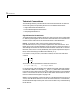
For instance, a 2-by-3 matrix, like matrix u below, has two rows and three
columns.
This matrix can be represented in MATLAB notation as
u = [1 2 3;4 5 6] % A 2-by-3 matrix
In the online help, matrix elements are indexed using either subscript notation
or MATLAB notation. For example, u
23
and u(2,3) both refer to the element
in the third column of the second row. The number of channels in a frame-based
matrix is the number of columns, N. More information about matrices can be
found in “Multichannel Signals” on page 3-11.
Vectors. Strictly speaking, a Simulink vector is a one-dimensional (1-D) array of
values, an ordered list that has no row or column orientation. For convenience,
the DSP Blockset help uses the plain term vector to refer to any of the following
three entities:
u
123
456
=