
User`s guide

4 DSP Operations
4-8
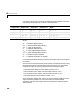
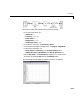
you specify a filter order. The other available parameters depend on the filter
type and band configuration, as shown in the table below.
where:
For all of the analog filter designs, frequency parameters are in units of radians
per second.
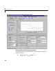
The block uses a state-space filter representation, and applies the filter using
the State-Space block in the Simulink Continuous library. All of the design
methods use Signal Processing Toolbox functions to design the filter:
•The Butterworth design uses the toolbox function
butter.
•The Chebyshev type I design uses the toolbox function
cheby1.
•The Chebyshev type II design uses the toolbox function
cheby2.
•The elliptic design uses the toolbox function
ellip.
The Analog Filter Design block is built on the filter design capabilities of the
Signal Processing Toolbox. For more information on the filter design
algorithms, see the Filter Designs section of the Signal Processing Toolbox
documentation.
Configuration Butterworth Chebyshev I Chebyshev II Elliptic
Lowpass
Ω
p
Ω
p
, R
p
Ω
s
, R
s
Ω
p
, R
p
, R
s
Highpass
Ω
p
Ω
p
, R
p
Ω
s
, R
s
Ω
p
, R
p
, R
s
Bandpass
Ω
p1
, Ω
p2
Ω
p1
, Ω
p2
, R
p
Ω
s1
, Ω
s2
, R
s
Ω
p1
, Ω
p2
, R
p
, R
s
Bandstop
Ω
p1
, Ω
p2
Ω
p1
, Ω
p2
, R
p
Ω
s1
, Ω
s2
, R
s
Ω
p1
, Ω
p2
, R
p
, R
s
Ω
p
= passband edge frequency
Ω
p1
= lower passband edge frequency
Ω
p2
= upper cutoff frequency
Ω
s
= stopband edge frequency
Ω
s1
= lower stopband edge frequency
Ω
s2
= upper stopband edge frequency
R
p
= passband ripple in decibels
R
s
= stopband attenuation in decibels