
User`s guide


3 Working with Signals
3-90
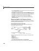
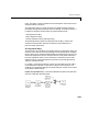
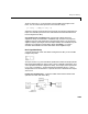
Use the default settings for the Digital Clock, Mux, and To Workspace blocks,
and adjust the Signal From Workspace block’s parameters to the values below:
•
Signal = 1:100
•Sample time = 1
•Samples per frame = 1
Set the DSP Constant block’s Constant value parameter to 3, and set the
Variable Integer Delay block’s
Initial conditions parameter to -1.
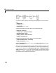
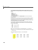
Now run the simulation and look at the output,
yout. The first few samples are
shown below.
The first column of
yout is the Simulink time provided by the Digital Clock
block, and the second column is the delayed input. As expected, the input to the
block at t=0 is delayed three samples, and appears as the fourth output sample,
at t=3. You can also see that the first three outputs from the Variable Integer
Delay block inherit the value of the block’s
Initial conditions parameter, -1.
This period of time, from the start of the simulation until the first input is
propagated to the output, is sometimes called the initial delay of the block.
Many blocks in the DSP Blockset have some degree of fixed or adjustable
algorithmic delay. These include any blocks whose algorithms rely on delay or
storage elements, such as filters or buffers. Often (but not always), such blocks
provide an
Initial conditions parameter that allows you to specify the output
values generated by the block during the initial delay. In other cases, the initial
conditions are internally fixed at 0.
Consult “DSP Block Reference” on page 5-1 for the delay characteristics of
particular DSP blocks.
yout =
0 -1
1 -1
2 -1
3 1
4 2
5 3
time