
User`s manual

Overview of the Serial Port
8-11
receiving a signal of a suitable frequency. CD is unasserted if the DCE is not
receiving a suitable signal.
RI is used to indicate the presence of an audible ringing signal. RI is asserted
when the DCE is receiving a ringing signal. RI is unasserted when the DCE is
not receiving a ringing signal (for example, it’s between rings).
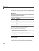
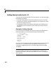
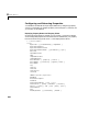
Serial Data Format
The serial data format includes one start bit, between five and eight data bits,
and one stop bit. A parity bit and an additional stop bit may be included in the
format as well. The diagram below illustrates the serial data format.
The format for serial port data is often expressed using the following notation
number of data bits - parity type - number of stop bits
For example, 8-N-1 is interpreted as eight data bits, no parity bit, and one stop
bit, while 7-E-2 is interpreted as seven data bits, even parity, and two stop bits.
The data bits are often referred to as a character since these bits usually
represent an ASCII character. The remaining bits are called framing bits since
they frame the data bits.
Bytes Versus Values
The collection of bits that comprise the serial data format is called a byte. At
first, this term may seem inaccurate since a byte is 8 bits and the serial data
format can range between 7 bits and 12 bits. However, when serial data is
stored on your computer, the framing bits are stripped away, and only the data
bits are retained. Moreover, eight data bits are always used regardless of the
number of data bits specified for transmission, with the unused bits assigned a
value of 0.
Start bit Data bits Parity bit Stop bits