
User`s manual

8 Serial Port I/O
8-8
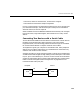
Note The serial port pin and signal assignments are with respect to the DTE.
For example, data is transmitted from the TD pin of the DTE to the RD pin of
the DCE.
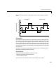
Signal States
Signals can be in either an active state or an inactive state. An active state
corresponds to the binary value 1, while an inactive state corresponds to the
binary value 0. An active signal state is often described as logic 1, on, true, or
a mark. An inactive signal state is often described as logic 0, off, false, or a
space.
For data signals, the “on” state occurs when the received signal voltage is more
negative than -3 volts, while the “off” state occurs for voltages more positive
than 3 volts. For control signals, the “on” state occurs when the received signal
voltage is more positive than 3 volts, while the “off” state occurs for voltages
more negative than -3 volts. The voltage between -3 volts and +3 volts is
considered a transition region, and the signal state is undefined.
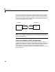
To bring the signal to the “on” state, the controlling device unasserts (or lowers)
the value for data pins and asserts (or raises) the value for control pins.
Conversely, to bring the signal to the “off” state, the controlling device asserts
the value for data pins and unasserts the value for control pins.