
User`s manual

Overview of the Serial Port
8-7
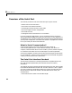
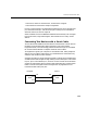
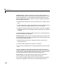
The pin assignment scheme for a 9-pin male connector on a DTE is given below.
The pins and signals associated with the 9-pin connector are described below.
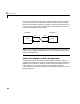
Refer to the RS-232 standard for a description of the signals and pin
assignments used for a 25-pin connector.
The term “data set” is synonymous with “modem” or “device,” while the term
“data terminal” is synonymous with “computer.”
Table 8-1: Serial Port Pin and Signal Assignments
Pin Label Signal Name Signal Type
1 CD Carrier Detect Control
2 RD Received Data Data
3 TD Transmitted Data Data
4 DTR Data Terminal Ready Control
5 GND Signal Ground Ground
6 DSR Data Set Ready Control
7 RTS Request to Send Control
8 CTS Clear to Send Control
9 RI Ring Indicator Control
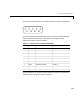
12345
678
9