
User`s manual

Overview of the Serial Port
8-5
•The names, electrical characteristics, and functions of signals
•The mechanical connections and pin assignments
Primary communication is accomplished using three pins: the Transmit Data
pin, the Receive Data pin, and the Ground pin. Other pins are available for
data flow control, but are not required.
Other standards such as RS-485 define additional functionality such as higher
bit transfer rates, longer cable lengths, and connections to as many as 256
devices.
Connecting Two Devices with a Serial Cable
The RS-232 standard defines the two devices connected with a serial cable as
the Data Terminal Equipment (DTE) and Data Circuit-Terminating
Equipment (DCE). This terminology reflects the RS-232 origin as a standard
for communication between a computer terminal and a modem.
Throughout this guide, your computer is considered a DTE, while peripheral
devices such as modems and printers are considered DCE’s. Note that many
scientific instruments function as DTE’s.
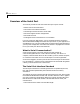
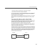
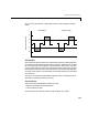
Since RS-232 mainly involves connecting a DTE to a DCE, the pin assignments
are defined such that straight-through cabling is used, where pin 1 is connected
to pin 1, pin 2 is connected to pin 2, and so on. A DTE to DCE serial connection
using the transmit data (TD) pin and the receive data (RD) pin is shown below.
Refer to “Serial Port Signals and Pin Assignments” on page 8-6 for more
information about serial port pins.
DTE
DCE
Pin 2
Pin 3
Pin 2
Pin 3
RD TD
TD RD
Computer Device