
User`s guide

Quick Start Tutorials
3-25
Tutorial 3: Code Verification
In this tutorial, you verify the answers computed by code generated from the
f14rtw model by comparing its outputs to the model outputs. You do this by
capturing data from runs of the Simulink model and the generated program
and comparing their respective values.
Note To obtain a valid comparison between outputs of the model and the
generated program, make sure that you have selected the same integration
scheme (
fixed-step, ode5 (Dormand-Prince)) and the same step size (0.05)
for both the Simulink run and the Real-Time Workshop build process. Also,
make sure that the model is configured to save simulation time, as in
Tutorial 2.
Logging Signals via Scope Blocks
This example uses Scope blocks (rather than Outport blocks) to log both input
and output data. The
f14rtw model should be configured as it was at the end
of the previous exercise, “Tutorial 2: Data Logging” on page 3-19.
To configure the Scope blocks to log data,
1 Before proceeding with this tutorial, clear the workspace and reload the
model so that the proper workspace variables are declared and initialized:
clear
f14rtw
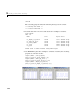
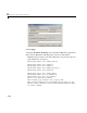
2 Open the Stick Input Scope block and click the Parameters button on the
toolbar of the Scope window. The
Stick Input parameters dialog opens.
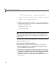
3 Select the Data History tab of the Scope Properties dialog.
4 Select the Save data to workspace option and enter the name of the
variable (
Stick_input) that is to receive the scope data. The dialog
appears as shown below.