Real-Time Workshop ® For Use with Simulink ® Getting Started Version 6
How to Contact The MathWorks: www.mathworks.com comp.soft-sys.matlab Web Newsgroup info@mathworks.com Technical support Product enhancement suggestions Bug reports Documentation error reports Order status, license renewals, passcodes Sales, pricing, and general information 508-647-7000 Phone 508-647-7001 Fax The MathWorks, Inc. 3 Apple Hill Drive Natick, MA 01760-2098 Mail support@mathworks.com suggest@mathworks.com bugs@mathworks.com doc@mathworks.com service@mathworks.
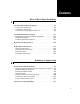
Contents What Is Real-Time Workshop? 1 Introducing Real-Time Workshop . . . . . . . . . . . . . . . . . . . . . . Components and Features . . . . . . . . . . . . . . . . . . . . . . . . . . . . . Capabilities and Benefits . . . . . . . . . . . . . . . . . . . . . . . . . . . . . . Accelerating Your Development Process . . . . . . . . . . . . . . . . . . 1-2 1-2 1-3 1-6 Installing Real-Time Workshop . . . . . . . . . . . . . . . . . . . . . . . Third-Party Compiler Installation on Windows . . . . . . . .
The Build Process . . . . . . . . . . . . . . . . . . . . . . . . . . . . . . . . . . . . Model Compilation . . . . . . . . . . . . . . . . . . . . . . . . . . . . . . . . . . . Code Generation . . . . . . . . . . . . . . . . . . . . . . . . . . . . . . . . . . . . . Customized Makefile Generation . . . . . . . . . . . . . . . . . . . . . . . Executable Program Generation . . . . . . . . . . . . . . . . . . . . . . . . Files and Directories Created by the Build Process . . . . . . . . .
Index iii
iv Contents
1 What Is Real-Time Workshop? This guide begins with a high-level overview of Real-Time Workshop®, describing its purpose, its component parts, its major features, and the ways in which it leverages the modeling power of Simulink® for developing real-time applications on a variety of platforms.
1 What Is Real-Time Workshop? Introducing Real-Time Workshop Real-Time Workshop® is an extension of capabilities of Simulink® and MATLAB® that automatically generates, packages and compiles source code from Simulink models to create real-time software applications on a variety of systems. By providing a code generation environment for rapid prototyping and deployment, Real-Time Workshop is the foundation for production code generation capabilities.
Introducing Real-Time Workshop embedded target products extend and tailor Real-Time Workshop code to run in a growing suite of microprocessor environments. • Rapid Simulations — Using Simulink Accelerator, the S-Function Target, or the Rapid Simulation Target, you can accelerate your simulations by 5 to 20 times on average. Executables built with these targets bypass normal Simulink interpretive simulation mode.
1 What Is Real-Time Workshop? - The flexible scripting capabilities of the Target Language Compiler enable you to fully customize generated code. - Efficient code for S-functions (user-created blocks) can be crafted using Target Language Compiler instructions (called TLC scripts) and automatically integrated with generated code.
Introducing Real-Time Workshop • Target support - Turnkey solutions for rapid prototyping substantially reduce design cycles, allowing for fast turnaround of design iterations. - Bundled rapid prototyping example targets provide working code you can modify and use quickly. - The optional Real-Time Windows and xPC targets for PC-based hardware from The MathWorks enable you to turn a PC with fast, high-quality, low-cost hardware into a rapid prototyping system.
1 What Is Real-Time Workshop? • Annotation of the generated code using the Description block property. • Control over naming and storage class for parameter and signal data, plus fully customizable custom storage class definitions and code generation methods. • Signal logging options and external parameter tuning, enabling easy interfacing of the generated code in your real-time system.
Introducing Real-Time Workshop System-Level Design Detailed Design Problem/Task Formulation FINISH START Software and Hardware Implementation Production and Manufacturing Testing Design Verification via Testing SPECIFICATION VERIFICATION DESIGN INTEGRATION SOFTWARE IMPLEMENTATION Spiral Design Process When you work with tools from The MathWorks, your model represents your understanding of your system.
1 What Is Real-Time Workshop? can verify that an algorithm works on a real-world rapid prototyping system. The spiral process lends itself naturally to parallelism in the overall development process. You can provide early working models to validation and production groups, involving them in your system development process from the start. Once unit models are prototyped, tested, and ready, they can be packaged into larger assemblies using Model blocks (the Simulink model referencing facility).
Introducing Real-Time Workshop Interactive design MATLAB and Toolboxes Interactive modeling and simulation Simulink Stateflow Blocksets Embedded Coder Deployed system Software integration Embedded Target Bat ch d esig n ve Rap rific id S atio imu n Tar lati on g e t Sy st em R de a T pi a r d ve l o pm ge P ts ro e ( r to t n t t ea y l-t pi esti ng im n g e) g in est tt ni et eu rg ar Ta ftw ed So dd be Em Customer-defined monitoring and parameter tuning, storage classes System testing and tuning
1 What Is Real-Time Workshop? Real-Time Windows Target or the xPC Target. With a rapid prototyping target, you connect your model to your physical system. This lets you locate design flaws and modeling errors quickly. After you have created your prototype system and have verified its outputs, you can use Real-Time Workshop Embedded Coder to deploy generated code on your custom target.
Installing Real-Time Workshop Installing Real-Time Workshop Your platform-specific MATLAB installation documentation provides all the information you need to install Real-Time Workshop. Prior to installing Real-Time Workshop, you must obtain a License File or Personal License Password from The MathWorks. The License File or Personal License Password (PLP) identifies the products you are permitted to install and use.
1 What Is Real-Time Workshop? Third-Party Compiler Installation on Windows Most Real-Time Workshop targets create an executable that runs on your workstation. When creating the executable, Real-Time Workshop must be able to access an appropriate compiler. The following sections describe how to configure your system so that Real-Time Workshop can access your compiler.
Installing Real-Time Workshop • Replace %INTELC71% with the root directory of the Intel Compiler installation. LCC The freeware LCC C compiler is shipped with MATLAB, and is installed with the product. If you want to use LCC to build programs generated by Real-Time Workshop, use the version that is currently shipped with the product. Information about LCC is available at http://www.cs.virginia.edu/~lcc-win32/.
1 What Is Real-Time Workshop? If the WATCOM environment variable is not defined, you must define it to point to where you installed your Watcom compiler. On Microsoft Windows 95 or 98, add set BORLAND= to your autoexec.bat file. On Microsoft Windows NT or 2000, in the control panel select System, click on the Advanced tab, select Environment, and define WATCOM to be the path to your compiler.
Installing Real-Time Workshop On UNIX. On UNIX, the Real-Time Workshop build process uses the default compiler. The cc compiler is the default on all platforms except SunOS, where gcc is the default. For further information, see Technical Note 1601, “What Compilers are Supported?” at http://www.mathworks.com/support/tech-notes/1600/1601.shtml.
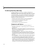
1 What Is Real-Time Workshop? Real-Time Workshop Demos A good way to familiarize yourself with Real-Time Workshop is by browsing through its suite of demos, running the ones of interest, and then inspecting code generated from these demo models. The demos illustrate many (but not all) Real-Time Workshop features. To access the current set of demos for Real-Time Workshop, click the link below or type rtwdemos at the MATLAB prompt.
Help and Documentation Help and Documentation Real-Time Workshop software is shipped with this Getting Started guide.
1 What Is Real-Time Workshop? 1 In the MATLAB window, click Desktop -> Help, Help -> Full product family help, or click the ? icon on the toolbar. The Help browser window opens. 2 In the left pane, click the Real-Time Workshop book icon. The Help browser displays the Real-Time Workshop Roadmap page in the right pane. Click on any link there, or click on the “+” sign to the left of the book icon in the left pane to reveal the table of contents.
Help and Documentation You can customize output from Real-Time Workshop at the block, target, and makefile levels. For advanced uses, you may have to prepare or modify Target Language Compiler files, as explained in the Target Language Compiler documentation.
1 What Is Real-Time Workshop? 1-20
2 Building an Application This chapter expands the high-level discussion of code generation and the build process given in Chapter 1, “What Is Real-Time Workshop?.” It provides a foundation of understanding for tutorial exercises in Chapter 3, “Working with Real-Time Workshop.” Real-Time Workshop Workflow (p. 2-2) Explains the typical workflow for applying Real-Time Workshop to the application development process Automatic Program Building (p.
2 Building an Application Real-Time Workshop Workflow The typical workflow for applying Real-Time Workshop to the application development process involves the following steps: 1 Map your application requirements to available configuration options. 2 Adjust configuration options, as necessary. 3 Run the Model Advisor Tool. 4 If necessary, tune configuration options based on the Model Advisor report. 5 Generate code for your model. 6 Repeat steps 2 to 6 if necessary. 7 Build an executable program image.
Real-Time Workshop Workflow Map Application Requirements to Configuration Options Adjust Configuration Settings Run Model Advisor Configuration Requires Tuning? Yes No Generate Code No Code OK? Yes Generate Code and Build Executable Program Verify Executable Program No Results Match Simulation ? Yes Name and save the Configuration Set Done 2-3
2 Building an Application Mapping Application Requirements to Configuration Options The first step to applying Real-Time Workshop to the application development process is to consider how your application requirements, particularly with respect to debugging, traceability, efficiency, and safety, map to code generation options available through the Simulink Configuration Parameters dialog. The following screen display shows the Real-Time Workshop pane of the Configuration Parameters dialog.
Real-Time Workshop Workflow • What is the highest priority for your application — traceability, efficiency, extra safety precaution, or some other criteria? • What is the second highest priority? • Can the priority at the start of the project differ from the priority required for the end result? What tradeoffs can be made? Once you have answered these questions, review the following table, which summarizes the impact of each configuration option on debugging, traceability, efficiency, and safety considerat
2 Building an Application Mapping of Application Requirements to Configuration Parameters (Continued) Configuration Parameter Debugging Traceability Efficiency Safety Precaution Factory Default Block reduction optimization Clear Clear Set No impact Set Implement logic signals as Boolean data (vs.
Real-Time Workshop Workflow Mapping of Application Requirements to Configuration Parameters (Continued) Configuration Parameter Debugging Traceability Efficiency Safety Precaution Factory Default No impact No impact Target specific No impact 8, 16, 32, 32 Set Set No impact No impact Clear Hardware Implementation Number of bits Real-Time Workshop Generate HTML report Real-Time Workshop: Comments Include comments Set Set No impact No impact Set Simulink block comments Set Set No im
2 Building an Application Mapping of Application Requirements to Configuration Parameters (Continued) Configuration Parameter Debugging Traceability Efficiency Safety Precaution Factory Default Utility function generation Shared Shared Shared No impact Auto* MAT-file variable name modifier No impact No impact No impact No impact rt_ * Backward compatibility with previous release.
Real-Time Workshop Workflow Although you can use the Model Advisor to improve model simulation, it is particularly useful for identifying aspects of your model that limit code efficiency or impede deployment of production code. The following figure shows part of a sample Model Advisor report. For more information on using the Model Advisor, see “Using the Model Advisor” of the Real-Time Workshop User’s Guide documentation.
2 Building an Application • You want to inspect the generated code. Is Real-Time Workshop generating what you expect? • You need to integrate custom handwritten code. • You want to experiment with configuration option settings. You specify code generation only by selecting the Generate code only option available on the Real-Time Workshop pane of the Configuration Parameters dialog (thus changing the label of the Build button to Generate code).
Real-Time Workshop Workflow For a more detailed discussion of the build process, see “Automatic Program Building” on page 2-13 and “The Build Process” on page 2-15. Verifying the Generated Results Once you have an executable image, run the image and compare the results to the results of your model’s simulation. You can do this by 1 Logging output data produced by simulation runs. 2 Logging output data produced by executable program runs.
2 Building an Application 5 Click Apply. The name of the active configuration in the Model Hierarchy pane changes to the name you typed. 6 Save the model. Adding and Copying Configuration Sets You might want to save the model with more than one configuration so that you can instantly reconfigure it at a later time.
Automatic Program Building Automatic Program Building Real-Time Workshop builds programs automatically for real-time applications in a variety of host environments. Using the make utility, Real-Time Workshop controls how it compiles and links the generated source code. The following figure illustrates the complete process. The shaded box highlights portions of the process that Real-Time Workshop executes.
2 Building an Application A high-level M-file command controls the Real-Time Workshop build process. By default, Real-Time Workshop issues the command make_rtw with appropriate options for most targets. You can customize this command by editing the contents of the Make command field in the Build process section of the Real-Time Workshop pane of the Configuration Parameters dialog. Do not issue the make_rtw command from the MATLAB Command Window.
The Build Process The Build Process Real-Time Workshop generates C code only or generates the C code and produces an executable image, depending on the level of processing you choose. By default, a Build button appears on the Real-Time Workshop pane of the Configuration Parameters dialog. This button completes the entire build process and an executable image results. If you select the Generate code only check box to the left of the button, the button label changes to Generate code.
2 Building an Application report contents vary depending on the target, but all reports feature clickable links to generated source files. The following display shows an example of an HTML code generation report for a generic real-time (GRT) target. For more information, see “Generate HTML Report” in the Real-Time Workshop User’s Guide documentation. You can also view an HTML report in Model Explorer. See the last part of “Tutorial 6: Generating Code for a Referenced Model” on page 3-51 for details.
The Build Process • Computes work vector sizes, such as those used by S-functions. (For more information about work vectors, refer to the Simulink Writing S-Functions documentation.) When Simulink completes this processing, Real-Time Workshop reads your model file (model.mdl) and compiles an intermediate representation of the model. This intermediate description is stored, in a language-independent format, in the ASCII file model.rtw. The model.rtw file is the input to the next stage of the build process.
2 Building an Application Note Real-Time Workshop executes all user-written S-function target files, but optionally executes block target files for Simulink blocks. 4 Writes a source code version of the Simulink block diagram. Customized Makefile Generation After generating the code, Real-Time Workshop generates a customized makefile, model.mk.
The Build Process Click Build Button model.c Simulink Model Generate Code Template Makefile Generate Makefile Create Executable? model.h model_private.h Custom Makefile model.mk No Yes Invoke make Stop During the final stage of processing, Real-Time Workshop invokes the generated make file, model.mk, which in turn compiles and links the generated code.
2 Building an Application This stage is optional, as illustrated by the control logic in the preceding figure. You might choose to omit this stage, for example, if you are targeting an embedded microcontroller or a digital signal processing (DSP) board. To omit this stage of processing, select the Generate code only option on the Real-Time Workshop pane of the Configuration Parameters dialog. You can then cross-compile your code and download it to your target hardware.
The Build Process Click Build Button model.c Simulink Model Generate Code Template Makefile Generate Makefile Create Executable? model.h model_private.h Custom Makefile model.
2 Building an Application Files and Directories Created by the Build Process The following sections discuss • “Files Created During Build Process” on page 2-22 • “Directories Used During the Build Process” on page 2-26 Files Created During Build Process This section lists model.* files created during the code generation and build process for the GRT and GRT malloc targets when used with stand-alone models.
The Build Process | rt_nonfinite.c | modelsources.txt | f14_dt.h | +---tlc | This directory contains TLC files generated during the build | process. These files are used to create the generated C source | and header files. ¦ +---html | This directory contains generated HTML files used for the Code | Generation report. Summary descriptions of the principle generated files follow: • model.rtw An ASCII file, representing the “compiled model,” generated by the Real-Time Workshop build process.
2 Building an Application - Exported Stateflow machine parented data - Model data structures, including rtM - Model entry point functions • model_private.h Contains local define constants and local data required by the model and subsystems. This file is included by the generated source files in the model. You do not need to include model_private.h when interfacing hand-written code to a model.
The Build Process • model.exe (on PC) or model (on UNIX), generated in current directory, not in build directory Executable program file created under control of the make utility by your development system (unless you have explicitly specified that Real-Time Workshop generate code only and skip the rest of the build process. • model.mk Customized makefile generated by the Real-Time Workshop build process. This file builds an executable program file. • rtmodel.
2 Building an Application • model_dt.h C header file used for supporting External Mode. Declares structures that contain data type and data type transition information for generated model data structures. • model_capi.h An interface header file between the model source code and the generated C-API. See “C-API for Interfacing with Signals and Parameters” in the Real-Time Workshop User’s Guide documentation for more information. • model_capi.
The Build Process • Project directory—slprj A subdirectory within your working directory. When models referenced via Model blocks are built for simulation or Real-Time Workshop code generation, files are placed in slprj. The Real-Time Workshop Embedded Coder has an option that places generated shared code in slprj without the use of Model Reference. Subdirectories in slprj provide separate places for simulation code, some Real-Time Workshop code, utility code shared between models, and other files.
2 Building an Application Shared Utilities Directory in the Build Process” in the Real-Time Workshop User’s Guide documentation.
The Build Process 2-29
2 Building an Application 2-30
3 Working with Real-Time Workshop This chapter provides an overview of the ideas and technology behind Real-Time Workshop, and hands-on exercises to help you to get started generating code as quickly as possible. It includes the following topics: Basic Real-Time Workshop Concepts (p. 3-2) Terms and definitions, such as host, target, code format, makefile, and more, used in the documentation Quick Start Tutorials (p.
3 Working with Real-Time Workshop Basic Real-Time Workshop Concepts Even if you have experience in building real-time systems, you may find it helpful to review the following descriptions to be sure of understanding the nomenclature that Real Time Workshop documentation uses. A more extensive list of terms may be found in the Glossary. The process of generating source code from Simulink models is shown in the following diagram. The terms and concepts involved are described below. Simulink model.
Basic Real-Time Workshop Concepts Target and Host A target is an environment—hardware or operating system—on which your generated code will run. The process of specifying this environment is called targeting. The process of generating target-specific code is controlled by a system target file, a template makefile, and a make command. To select a desired target, you can specify these items individually, or you can choose from a wide variety of ready-to-run configurations.
3 Working with Real-Time Workshop The Generic Real-Time Target Real-Time Workshop provides a generic real-time development target. The GRT target provides an environment for simulating fixed-step models in single or multitasking mode. A program generated with the GRT target runs your model, in simulated time, as a stand-alone program on your workstation. The target supports external mode, allowing your application to compute outputs and send them back to Simulink for you to view.
Basic Real-Time Workshop Concepts Template Makefiles Real-Time Workshop uses template makefiles to build an executable from the generated code. The Real-Time Workshop build process creates a makefile from the template makefile. Each line from the template makefile is copied into the makefile; tokens encountered during this process are expanded into the makefile. The name of the makefile created by the build process is model.mk (where model is the name of the Simulink model). The model.
3 Working with Real-Time Workshop 4 Finally, make is invoked. make compiles and links a program from the generated code, as instructed in the generated makefile. “Automatic Program Building” on page 2-13 gives an overview of the build process. “Simulation Parameters and Code Generation” in the Real-Time Workshop User’s Guide documentation expands on how model data affects code generation.
Quick Start Tutorials Quick Start Tutorials This section provides hands-on experience with the code generation, program building, data logging, code verification, and external mode capabilities of Real-Time Workshop.
3 Working with Real-Time Workshop Compilers” on page 1-14 for more information on supported compilers and compiler installation. The f14 Demonstration Model Tutorials 1 through 3 use a demonstration Simulink model, f14.mdl, from the matlabroot/toolbox/simulink/simdemos/aerospace directory. (By default, this directory is on your MATLAB path; matlabroot is the location of MATLAB on your system.) f14 is a model of a flight controller for the longitudinal motion of a Grumman Aerospace F-14 aircraft.
Quick Start Tutorials Tutorial 1: Building a Generic Real-Time Program This tutorial walks through the process of generating C code and building an executable program from the demonstration model. The resultant stand-alone program runs on your workstation, independent of external timing and events. Working and Build Directories It is convenient to work with a local copy of the f14 model, stored in its own directory, f14example. This discussion assumes that the f14example directory resides on drive d:.
3 Working with Real-Time Workshop Note When a model contains Model blocks (which enable one Simulink model to include others), special project directories are created in your working directory to organize code for referenced models. Project directories exist alongside of Real-Time Workshop build directories, and are always named /slprj. “Tutorial 6: Generating Code for a Referenced Model” on page 3-51 describes navigating project directory structures in Model Explorer.
Quick Start Tutorials Mode: SingleTasking The Solver pane with the modified parameter settings is shown below. Note the tan background color of the controls you just changed; use this visual feedback to double-check that what you set is what you intended. When you apply your changes, the background color reverts to white. Note There are several ways in which can access simulation and code generation parameters.
3 Working with Real-Time Workshop Selecting the Target Configuration Note The steps in this section do not require you to make changes. They are included to help you familiarize yourself with the Real-Time Workshop user interface. As you step through the dialogs, place the mouse pointer on any item of interest to see a tooltip describing its function. To specify the desired target configuration, you choose a system target file, a template makefile, and a make command.
Quick Start Tutorials 4 From the list of available configurations, select Generic Real-Time Target (as shown above) and then click OK. Note The System Target File Browser lists all system target files found on the MATLAB path. Some of these may require additional licensed products (for example, Real-Time Workshop Embedded Coder) in order to use them. The Real-Time Workshop pane displays the correct system target file (grt.
3 Working with Real-Time Workshop 5 Select the Debug tab of the Real-Time Workshop dialog. The options displayed here control build verbosity and debugging support, and are common to all target configurations. Make sure that all options are set to their defaults, as shown below.
Quick Start Tutorials 6 Select the Symbols tab of the Real-Time Workshop dialog. The options on this pane control the look and feel of generated code; there is only one for the GRT target, Maximum identifier length (the number of characters allowed in variable and other symbol names). The default for this option is 31, as shown below.
3 Working with Real-Time Workshop 7 Select the Comments tab of the Real-Time Workshop dialog. The options displayed here control the types of comments included in generated code. The default is to include only block-level comments, as shown below.
Quick Start Tutorials 8 Make sure that the Generate code only option is not selected, and save the model. Building and Running the Program The Real-Time Workshop build process generates C code from the model, and then compiles and links the generated program to create an executable image. To build and run the program, 1 Click the Build button in the Configuration Parameters dialog to start the build process.
3 Working with Real-Time Workshop The content of many of the succeeding messages depends on your compiler and operating system. The final message is ### Successful completion of Real-Time Workshop build procedure for model: f14rtw 3 The working directory now contains an executable, f14rtw.exe (on PC) or f14rtw (on UNIX). In addition, a build directory, f14rtw_grt_rtw, has been created in your working directory.
Quick Start Tutorials f14rtw_grt_rtw contains these generated source files: f14rtw.c Stand-alone C code that implements the model f14rtw_data.c Initial parameter values used by the model rt_nonfinite.c Function to initialize nonfinite types (Inf, NaN and -Inf) f14rtw.h An include header file containing definitions of parameter and state variables f14rtw_types.h Forward declarations of data types used in the code f14rtw_private.h Header file containing common include definitions rt_nonfinite.
3 Working with Real-Time Workshop To configure data logging, you use the Data Import/Export pane of the Configuration Parameters dialog. The process is the same as configuring a Simulink model to save output to the MATLAB workspace. In addition, however, for each workspace return variable you define and enable, Real-Time Workshop defines a parallel MAT-file variable. For example, if you save simulation time to the variable tout, your generated program logs the same data to a variable named rt_tout.
Quick Start Tutorials enables Real-Time Workshop to generate code that logs the simulation time to the MAT-file with a related name, as you will see below. 4 Select the Output option. This tells Simulink to save time step data during simulation as a variable named yout. Selecting Output enables Real-Time Workshop to generate code that logs the root Output blocks (Angle of Attack and Pilot G Force) to the MAT-file with a related name, as you will see below.
3 Working with Real-Time Workshop 8 Verify that the simulation time and outputs have been saved to the workspace. whos *out Name tout yout Size 601x1 601x2 Bytes 4808 9616 Class double array double array Grand total is 1803 elements using 14424 bytes 9 Verify that Pilot G Force was correctly logged by plotting simulation time versus that variable. plot(tout,yout(:,2)) The resulting plot is shown below.
Quick Start Tutorials Part 2: Data Logging from Generated Code In the second part of the exercise, you build and run a Real-Time Workshop executable of the f14rtw model which outputs a MAT-file containing the variables that you logged in part 1. Even if you have already generated code for the F14rtw model, code for it must be regenerated because you have changed the model by enabling data logging. The steps below explain this.
3 Working with Real-Time Workshop 4 Click Apply to register your changes. 5 Generate code and build an executable: Click the Build button, type Ctrl+B, or select Build Model... from the Real-Time Workshop sub-menu of the Tools menu in the model window. 6 When the build concludes, run the executable with the command !f14rtw 7 The program now produces two message lines, indicating that the MAT-file has been written. ** starting the model ** ** created f14rtw.
Quick Start Tutorials Tutorial 3: Code Verification In this tutorial, you verify the answers computed by code generated from the f14rtw model by comparing its outputs to the model outputs. You do this by capturing data from runs of the Simulink model and the generated program and comparing their respective values.
3 Working with Real-Time Workshop The Stick Input signal to the scope block is logged to the array Stick_input during simulation. The generated code logs the same signal data to the MAT-file variable Stick_input_rt during a run of the executable program. 5 Click the Apply button. 6 Configure the Pilot G Force and Angle of Attack Scope blocks similarly, using the variable names Pilot_G_force and Angle_of_attack. 7 Save the model.
Quick Start Tutorials 3 Use the whos command to observe that the array variables Stick_input, Pilot_G_force, and Angle_of_attack have been saved to the workspace. 4 Plot one or more of the logged variables against simulation time. For example, plot(tout, Stick_input(:,2)) Logging Data from the Generated Program Since you have modified the model, you must rebuild and run the f14rtw executable in order to obtain a valid data file: 1 Set the variable name modifier to be used by Real-Time Workshop.
3 Working with Real-Time Workshop !f14rtw The executing program writes the following messages to the console. ** starting the model ** ** created f14rtw.mat ** 6 Load the data file f14rtw.mat and observe the workspace variables.
Quick Start Tutorials Comparing Numerical Results of the Simulation and the Generated Program Your Simulink simulations and the generated code should produce nearly identical output. You have now obtained data from a Simulink run of the model, and from a run of the program generated from the model. It is a simple matter to compare the f14rtw model output to the results achieved by Real-Time Workshop.
3 Working with Real-Time Workshop Tutorial 4: A First Look at Generated Code In this tutorial, you examine code generated from a simple model to observe the effects of some of the many code optimization features available in Real-Time Workshop. Note You can view the code generated from this example using the MATLAB editor. You can also view the code in the MATLAB Help browser if you enable the Create HTML report option before generating code.
Quick Start Tutorials 5 Click the Solver tab and enter the following parameter values on the Solver pane: Solver options: set Type to Fixed-step. Select the ode5 (Dormand-Prince) solver algorithm. Leave the other Solver pane parameters set to their default values. 6 Click Apply. 7 Click the Data Import/Export tab and make sure all check boxes are cleared. 8 Click Apply if you made any changes to the pane. 9 Click the Real-Time Workshop node in the Contents pane.
3 Working with Real-Time Workshop 2 Click Apply. 3 Click the Real-Time Workshop node and click the Generate code button. 4 Because the Generate code only option was selected, Real-Time Workshop does not invoke your make utility. The code generation process ends with this set of messages: ### . ### ### ### ### . ### ### ### ### ### ### ### for 3-32 Writing header file example_types.h Writing Writing Writing Writing header source header header file file file file example.h example.c example_private.
Quick Start Tutorials 5 The generated code is in the build directory, example_grt_rtw. The file example_grt_rtw\example.c contains the output computation for the model. Open this file into the MATLAB editor: edit example_grt_rtw\example.c 6 In example.c, find the function example_output near the top of the file. The generated C code consists of procedures that implement the algorithms defined by your Simulink block diagram.
3 Working with Real-Time Workshop example_P.SineWave_Phase) + example_P.SineWave_Bias; example_B.gain_out = example_B.sin_out * example_P.Gain_Gain; example_Y.Out1 = example_B.gain_out; } 7 In GRT targets such as this, the function example_output is called by a wrapper function, MdlOutputs. In example.c, find the function MdlOutputs near the end.
Quick Start Tutorials You will observe the effects of expression folding later in this tutorial. Not performing expression folding allows you to see the effects of the block output optimizations. 3 Click Apply to apply the new settings. 4 Click Generate Code, or type Ctrl+B in the model window to generate code again. As before, Real-Time Workshop generates code in the example_grt_rtw directory. Note that the previously generated code is overwritten. 5 Edit example_grt_rtw/example.
3 Working with Real-Time Workshop sin(example_P.SineWave_Freq * example_M->Timing.t[0] + example_P.SineWave_Phase) + example_P.SineWave_Bias; rtb_gain_out = rtb_sin_out * example_P.Gain_Gain; example_Y.Out1 = rtb_gain_out; } This code is more efficient in terms of memory usage. The efficiency improvement gained by enabling Enable local block outputs and Reuse block outputs would be more significant in a large model with many signals.
Quick Start Tutorials 4 Click the Generate code button. 5 As before, Real-Time Workshop generates code in the example_grt_rtw directory. 6 Edit example_grt_rtw/example.c and examine the function example_output. In the previous examples, the Gain block computation was computed in a separate code statement and the result was stored in a temporary location before the final output computation.
3 Working with Real-Time Workshop Enabling this option causes Real-Time Workshop to produce an HTML file for each generated source file, plus a summary and an index file, in a directory named /html within the build directory. If the Launch report after code generation completes option (which is enabled by selecting Generate HTML report) is also selected, the HTML summary and index are automatically loaded into a new browser window and displayed.
Quick Start Tutorials you can navigate to identify the settings of every option in place at the time that the HTML report was generated. You can refer to HTML reports at any time. To review an existing HTML report after you have closed its window, use any HTML browser to open the file html/model_codgen_rpt.html within your build directory. Note The contents of HTML reports for different target types vary, and reports for models with subsystems feature additional information.
3 Working with Real-Time Workshop The example presented uses the generic real-time target, and does not require any hardware other than the computer on which you run Simulink and Real-Time Workshop. The generated executable in this example runs on the host computer under a separate process from MATLAB and Simulink. The procedures for building, running, and testing your programs are almost identical in UNIX and PC environments. The discussion notes differences where applicable.
Quick Start Tutorials 4 Define and assign two variables A and B in the MATLAB workspace as follows: A = 2; B = 3; 5 Open Gain block A and set its Gain parameter to the variable A as shown below. 6 Similarly, open Gain block B and set its Gain parameter to the variable B.
3 Working with Real-Time Workshop 8 From the File menu, choose Save As. Save the model as ext_example.mdl. Part 2: Building the Target Executable In this section, you set up the model and code generation parameters required for an external mode compatible target program. Then you generate code and build the target executable: 1 Open the Configuration Parameters dialog from the Simulation menu.
Quick Start Tutorials 2 Click the Data Import/Export tab, and clear the Time and Output check boxes. In this exercise, data is not logged to the workspace or to a MAT-file. 3 Click the Optimization tab. Make sure that the Inline parameters option (under the Code generation - parameters pane) is not selected. Although external mode supports inlined parameters, you will not explore this in this exercise. 4 Click the Real-Time Workshop configuration node in the Select column.
3 Working with Real-Time Workshop External mode supports communication via TCP/IP, serial, and custom transport protocols. The MEX-file name field specifies the name of a MEX-file that implements host and target communications on the host side. The default for TCP/IP is ext_comm, a MEX-file provided by Real-Time Workshop. You can override this default by supplying appropriate files.
Quick Start Tutorials 7 Click Apply to save the Interface settings. 8 Save the model. 9 In the Real-Time Workshop pane, click Build to generate code and create the target program. The content of subsequent messages depends on your compiler and operating system.The final message is ### Successful completion of Real-Time Workshop build procedure for model: ext_example In the next section, you will run the ext_example executable and use Simulink as an interactive front end to the running target program.
3 Working with Real-Time Workshop The top three buttons are for use after the target program has started. The two lower buttons open separate dialogs: - The Signal & triggering button opens the External Signal & Triggering dialog, which configures which signals are viewed and how signals are acquired. - The Data archiving button opens the External Data Archiving dialog. Data archiving lets you save data sets generated by the target program for future analysis. This example does not use data archiving.
Quick Start Tutorials 4 Make sure that the External Signal & Triggering dialog is set to the defaults as shown: - Select all check box is selected. All signals in the Signal selection list are marked with an X in the Block column.
3 Working with Real-Time Workshop Click Close, and then close the External Mode Control Panel. For information on the options mentioned above, see “External Signal Uploading and Triggering” in the Real-Time Workshop User’s Guide documentation. 5 To run the target program, you must open a command prompt window (on UNIX systems, an Xterm window). At the command prompt, change to the ext_mode_example directory that you created in step 1. The target program is in this directory.
Quick Start Tutorials 6 Open Scope blocks A and B. At this point, no signals are visible on the scopes. When you connect Simulink to the target program and begin model execution, the signals generated by the target program will be visible on the scope displays. 7 The model itself must be in external mode before communication between the model and the target program can begin.
3 Working with Real-Time Workshop Part 4: Tuning Parameters You can change the gain factor of either Gain block by assigning a new value to the variables A or B in the MATLAB workspace. When you change block parameter values in the workspace during a simulation, you must explicitly update the block diagram with these changes. When the block diagram is updated, the new values are downloaded to the target program.
Quick Start Tutorials Tutorial 6: Generating Code for a Referenced Model The Model block, introduced in Version 6 of Simulink, enables an existing Simulink model to be used as a block in another model. When a model contains one or more Model blocks, we call it a top model. Models represented by model blocks are called referenced models in that context. Model blocks are particularly useful for large-scale modeling applications.
3 Working with Real-Time Workshop 4 Right-click any of the three highlighted blocks and select Create Subsystem from the pop-up context menu. You can also select Create Subsystem from the Edit menu or type Ctrl+G instead of right-clicking. 5 If the new Subsystem block is not where you want it, move it to a preferred location. Rename the block vdpmult. 6 Right-click the vdpmult block and select SubSystem Parameters. A Block Parameters dialog appears.
Quick Start Tutorials The border of the vdpmult subsystem thickens to indicate that it is now atomic. An atomic subsystem executes as a unit rather than having its blocks executed at different stages during simulation. This makes it possible to abstract subsystems as stand-alone models and as functions in generated code. The block diagram now looks like this.
3 Working with Real-Time Workshop 8 Open the Configuration Parameters dialog from the Simulation menu or by typing Ctrl+E. The next four steps bypass certain model reference error checks, to minimize the number of times code must be generated later on. 9 In the Select pane, select Solver. In the Dialog pane, change the Solver Type to Fixed-step and click Apply. Fixed-step solvers must be used when generating code, although referenced models can use different solvers than top models.
Quick Start Tutorials In this exercise you only supply the first two calling arguments (a model name and a target directory) and no return arguments: 1 Run the conversion utility by typing at the MATLAB prompt sl_convert_to_model_reference('vdptop','.') This converts the vdptop model and places the resulting files in the current directory. The converter prints a number of progress messages to the console, and when successful, terminates with ans = 1 Note that the model being converted need not be open.
3 Working with Real-Time Workshop Code for model reference simulation targets is placed in the slprj/sim subdirectory. Generated code for GRT, ERT, and other Real-Time Workshop targets is placed in slprj subdirectories named for those targets. You will inspect some model reference code later in this exercise. For more information on project directories, see “Working with Project Directories” on page 3–62.
Quick Start Tutorials This instructs the vdptop_converted model (and later its executable) to log time and output data to MAT-files for each time step. 5 Generate GRT code (the default) and an executable for the top model and the referenced model. To start the build process, do one of the following: - Select the Real-Time Workshop configuration parameter pane and click Build, - Choose Real-Time Workshop->Build Model from the Model’s Tools menu, or - Type Ctrl+B.
3 Working with Real-Time Workshop 6 Use the Model Explorer to inspect the newly created build directory, vdptop_converted_grt_rtw, in your current directory. Choose Model Explorer from the View menu. 7 In Model Explorer’s Model Hierarchy pane, expand the node for the vdptop_converted model. 8 Click the plus sign in front of the node named Code for vdptop_converted to expand the node. 9 Click the Top Model node that appears directly under the Code for vdptop_converted node.
Quick Start Tutorials To view a model’s generated code in Model Explorer, the model must be open. To open a file in a text editor, click a filename, and then click the hyperlink that appears in the gray area at the top of the Dialog pane. 10 Examine code for vdpmult.mdl. In the Model Hierarchy pane of Model Explorer, right-click the Model block icon labeled vdpmult (vdpmult) and select Open Model 'vdpmult' from the menu that appears.
3 Working with Real-Time Workshop 11 A Model Explorer node named Code for vdpmult also appears under the node Code for vdptop_converted. Expand this node by clicking its plus sign, and then select vdpmult below it. Model Explorer now shows the files for the referenced model (which are in the /slprj/grt directory). 12 Click vdpmult.c in the Contents pane to view the model’s output and initialization functions in the Dialog pane. Here is the code for the vdpmult output function.
Quick Start Tutorials /* Output and update for referenced model: 'vdpmult'*/ void mr_vdpmult(const real_T *rtu_0, const real_T *rtu_1, real_T *rty_0, RT_MODEL_vdpmult *vdpmult_M) { /* local block i/o variables */ /* Gain: '/Mu' incorporates: * Fcn: '/Fcn' * Product: '/Product' */ (*rty_0) = (1.0 - (*rtu_0) * (*rtu_0)) * (*rtu_1); /* Update absolute time for base rate */ if(!(++vdpmult_M->Timing.clockTick0)) ++vdpmult_M->Timing.
3 Working with Real-Time Workshop Working with Project Directories When you view generated code in Model Explorer, the files listed in the Contents pane can exist either in a build directory or a project directory. Model reference project directories (always rooted under slprj), like build directories, are created in your current working directory, and this implies certain constraints on when and where model reference targets are built, and how they are accessed.
Quick Start Tutorials 3-63
3 Working with Real-Time Workshop 3-64
Glossary application modules With respect to Real-Time Workshop program architecture, these are collections of programs that implement functions carried out by the system-dependent, system-independent, and application components. atomic subsystem Subsystem whose blocks are executed as a unit before moving on. Conditionally executed subsystems are atomic, and atomic subsystems are nonvirtual. Unconditionally executed subsystems are virtual by default, but can be designated as atomic.
expression folding Code optimization technique that minimizes the computation of intermediate results at block outputs and the storage of such results in temporary buffers or variables. It can dramatically improve the efficiency of generated code, achieving results that compare favorably with hand-optimized code. file extensions The table below lists the file extensions associated with Simulink, the Target Language Compiler, and Real-Time Workshop.
Glossary host system Computer system on which you create and may compile your real-time application. Also referred to as emulation hardware. inline Generally, this means to place something directly in the generated source code. You can inline parameters and S-functions using Real-Time Workshop and the Target Language Compiler. inlined parameters (Target Language Compiler Boolean global variable: InlineParameters) The numerical values of the block parameters are hard-coded into the generated code.
part of a Simulink model, it is by default noninlined unless you write your own .tlc file that inlines it. nonreal-time Simulation environment of a block diagram provided for high-speed simulation of your model. Execution is not tied to a real-time clock. nonvirtual block Any block that performs some algorithm, such as a Gain block. Real-Time Workshop generates code for all nonvirtual blocks, either inline or as separate functions and files, as directed by users.
Glossary simulation target Set of code files generated for a model which is referenced by a Model block. Simulation target code is generated into /slprj/sim project directory in the working directory. Also an executable library compiled from these codes that implements a Model block. See also Real-Time Workshop Target. singletasking Mode in which a model runs in one task, regardless of the number of sample rates it contains.
virtual block Connection or graphical block, for example a Mux block, that has no algorithmic functionality. Virtual blocks incur no real-time overhead as no code is generated for them. work vector Data structures for saving internal states or similar information, accessible to blocks that may require such work areas. These include state work (rtDWork), real work (rtRWork), integer work (rtIWork), and pointer work (rtPWork) structures.
Index B block target file 2-17 build directory contents of 2-27 f14 example 3-18 naming convention 2-26 build process steps in 2-15 C code format definition of 3-3 code generation tutorial 3-30 code verification tutorial 3-25 compilers optimization settings 1-15 supported on UNIX 1-15 supported on Windows 1-14 D data logging from generated code 3-27 tutorial 3-19 via Scope blocks example 3-25 directories build 3-9 working 3-9 documentation online 1-17 printing 1-18 E external mode building executable 3-4
Index subsystem.c 2-24 R subsystem.
Index system target file 3-4 TLC scripts 2-17 template makefile introduction to 3-5 tutorials building generic real-time program 3-9 code generation 3-30 code verification 3-25 data logging 3-19 external mode 3-39 model referencing 3-51 W working directory 3-9 Index-3
Index Index-4