
User`s guide

Building Generic Real-Time Programs
2-13
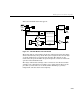
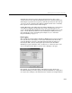
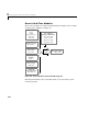
This is the Simulink model that appears:
Figure 2-1: Simulink Model of an F14 Aircraft
The model employs a Signal Generator block to simulate the pilot’s stick input,
which is monitored by a Scope block. The system outputs are the aircraft angle
of attack and the G forces experienced by the pilot. The outputs are also
monitored by Scope blocks. These Scope blocks provide a means to monitor the
operation of the Simulink model.
The design and internal workings of the
f14 model are not discussed in this
example; such a discussion is beyond the scope of this manual. However, the
procedure you must follow to use the Real-Time Workshop is generally
independent of model content and complexity.
q
2
Nz Pilot (g)
1
alpha (rad)
Stick Input
Pilot G force
Scope
Pilot
w
q
Pilot g force (g)
Nz pilot
calculation
1/Uo
Mw
Mq
Zw
Wg
Qg
Dryden Wind
Gust Models
Stick Input (in)
alpha (rad)
q (rad/sec)
Elevator Command (deg)
Controller
Angle of
Attack
Elevator Deflection d (deg)
Vertical Gust wGust (ft/sec)
Rotary Gust qGust (rad/sec)
Vertical Velocity w (ft/sec)
Pitch Rate q (rad/sec)
Aircraft
Dynamics
Model
1
Ta.s+1
Actuator
Model
1
u
w
qGust
wGust
q