
User`s guide

The Rapid Prototyping Process
1-11
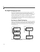
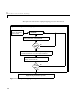
Algorithm Design and Analysis
From the block diagrams developed during the modeling stage, you can extract
state-space models through linearization techniques. These matrices can be
used in control system design. You can use these toolboxes to facilitate control
system design, and work with the matrices that you derived:
• Control System Toolbox
• Robust Control Toolbox
• Model Predictive Control Toolbox
• µ-Analysis and Synthesis Toolbox
• LMI Control Toolbox
• QFT Control Toolbox
Once you have your controller designed, you can create a closed-loop system by
connecting it to the Simulink plant model. Closed-loop simulations allow you
to determine how well the initial design meets performance requirements.
Once you have a model that you’re satisfied with, it is a simple matter to
generate C code directly from the Simulink block diagram, compile it for the
target processor, and link it with supplied or user-written application modules.
Analyzing Results, Parameter Tuning, and Signal Monitoring
Using External Mode
You can load the program data into MATLAB for analysis or display the data
with third party monitoring tools. You can easily make design changes to the
Simulink model and then regenerate the C code.
After building the executable and downloading it to your hardware, you can
tune (modify) block parameters in Simulink and automatically download the
new values to the hardware. To change these parameters from the Simulink
block diagram, you can run Simulink in external mode. Simulink’s external
mode allows you to change parameters interactively without stopping the
real-time execution of the model on the hardware.
You can monitor signals using Scope blocks while running external mode.
Simply connect Scope blocks to signals that you want to monitor. You can then
view signals changing as you tune parameters on-the-fly.