
User`s guide


14 Real-Time Workshop Ada Coder
14-18
Code Validation
After completing the build process, the stand-alone version of the
countersdemo model is ready for comparison with the Simulink model. The
data logging options selected with the
Real-time Options dialog box cause the
program to save the control signal, enabled counter, triggered counter, and
simulation time. You can now use M
ATLAB to produce plots of the same data
that you see on the three Simulink scopes.
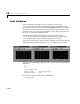
In both the Simulink and the stand-alone executable version of the
countersdemo model, the control input is simulated with a discrete-pulse
generator producing a 10 Hz, fifty percent duty cycle waveform.
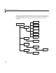
Opening the control signal, enabled counter, and triggered counter scopes and
running the Simulink simulation from
T=0 to T=2 produces these outputs.
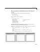
Type
who at the MATLAB prompt to view the variable names from Simulink
simulation:
who
Your variables are:
Enable_Signal Triggered_Counter
Enabled_Counter tout
Now run the stand-alone program from MATLAB:
!countersdemo