
User`s guide

11 Real-Time Workshop Libraries
11-10
subsystem (or Stateflow Chart). The Asynchronous Interrupt block then
installs the Task Synchronization block as the ISR, which releases a
synchronization semaphore (performs a
semGive) to the function-call
subsystem and returns. See the VxWorks Task Synchronization block for more
information.
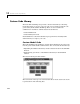
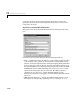
Using the Asynchronous Interrupt Block
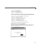
The Asynchronous Interrupt block has two modes: RTW and Simulation;
• In RTW mode, the Asynchronous Interrupt block configures the downstream
system as an ISR and enables interrupts during model startup. You can
select this mode using the Asynchronous Interrupt block dialog box when
generating code.
• In Simulation mode, simulated Interrupt Request (IRQ) signals are routed
through the Asynchronous Interrupt block’s trigger port. Upon receiving a
simulated interrupt, the block calls the associated system.
You should select this mode when simulating, in Simulink, the effects of an
interrupt signal. Note that there can only be one VxWorks Asynchronous
Interrupt block in a model and all desired interrupts should be configured by
it.
In both RTW and Simulation mode, in the event that two IRQ signals occur
simultaneously, the Asynchronous Interrupt block executes the downstream
systems according to their priority interrupt level.
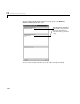
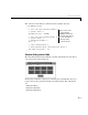
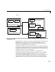
The Asynchronous Interrupt block provides these two modes to make the
development and implementation of real-time systems that include ISRs easier
and quicker. You can develop two models, one that includes a plant and a
controller for simulation, and one that only includes the controller for code
generation. Using the Library feature of Simulink, you can implement changes
to both models simultaneously. This picture illustrates the