
User`s guide

Device Driver Blocks
9-15
executed at the specified rate. Specifically, when the digital output block is
executed, it causes corresponding boolean values to be output from the
board’s digital I/O channels.
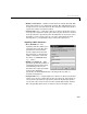
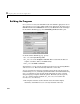
Adding Device Driver Blocks to the Model
Add device driver blocks to the Simulink block diagram as you would any other
block — simply drag the block from the block library and insert it into the
model. Connect the ADC or Digital Input module to the model’s inputs and
connect the DAC or Digital Output module to the model’s outputs.
Including Device Driver Code
Device driver blocks are implemented as S-functions written in C. The C code
for a device driver block is compiled as a MEX-file so that it can be called by
Simulink. See the MATLAB Application Program Interface Guide for
information on MEX-files.
ThesameCcodecanalsobecompiledandlinkedtothegeneratedcodejustlike
any other C-coded, S-function. However, by using the target (
.tlc)filethat
corresponds to each of the C file S-functions, the device driver code is inlined in
the generated code.
The
matlabroot\rtw\c\dos\devices directory contains the MEX-files, C files,
and target files (
.tlc) for the device driver blocks included in doslib.This
directory is automatically added to your MATLAB path when you include any
of the blocks from
doslib in your model.