
User`s guide

9 Targeting DOS for Real-Time Applications
9-14
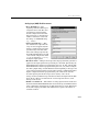
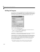
Digital Output Block Parameters
• Base I/O Address —The
beginning of the I/O address space
assigned to the board. The value
specified here must match the
board’s configuration. Note that
this parameter is a hexadecimal
number and must be entered in
the dialog as a MATLAB string
(e.g.,
'0x300').
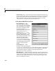
• Low/High Threshold Values —
This parameter specifies the
threshold levels,
[lo hi],for
converting the block inputs into
0/1 digital values. The signal in
the block diagram connected to
the block input should rise above
the high threshold level for a
0 to 1 transition in the
corresponding Digital Output
Channel on the I/O board.
Similarly, the input should fall
below the low threshold level for a 1 to 0 transition.
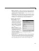
• Initial Output(s) — Same as the Analog Output block, except the specified
values are converted to 0 or 1 based on the lower threshold value before they
are written to the corresponding digital output channel.
• Final Output(s) — Same as the Analog Output block, except the specified
values are converted to 0 or 1 based on the lower threshold value before they
are written to the corresponding digital output channel on the I/O board.
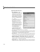
• Number of Channels — This parameter specifies the number of 1-bit
digital I/O channels being enabled. This parameter also determines the
output port width of the block. Specifically, the DAS-1600/1400 Series boards
provide four bits (i.e., channels) for digital I/O.
• Sample Time (sec) — Digital output device drivers are discrete blocks that
require you to specify a sample time. In the generated code, these blocks are