
User`s guide


Device Driver Blocks
9-13
• Number of Channels — Number of DAC channels enabled. The DAS-1600
Series I/O boards have two 12-bit DAC channels. The DAS-1400 Series I/O
boards do not have any DAC channels. The input port width of this block is
equal to the number of channels enabled.
• Sample Time (sec) — DAC device drivers are discrete blocks that require
you to specify a sample time. In the generated code, these blocks are executed
at the specified rate. Specifically, when the DAC block is executed, it causes
the DAC to convert a single value on each of the enabled DAC channels,
which produces a corresponding voltage on the DAC output pin(s).
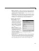
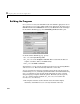
Digital Input Block Parameters
• Base I/O Address —The
beginning of the I/O address space
assigned to the board. The value
specified here must match the
board’s configuration. Note that
this parameter is a hexadecimal
number and must be entered in
the dialog as a MATLAB string
(e.g.,
'0x300').
• Number of Channels —This
parameter specifies the number of
1-bit digital input channels being
enabled. This parameter also
determines the output port width
of the block in Simulink.
Specifically, the DAS-1600/1400 Series boards provide four bits (i.e.,
channels) for digital I/O.
• Sample Time (sec) — Digital input device drivers are discrete blocks that
require you to specify a sample time. In the generated code, these blocks are
executed at the specified rate. Specifically, when the digital input block is
executed, it reads a boolean value from the enabled digital input channels.
The corresponding input values are written to the block output vector.