
User`s guide


9 Targeting DOS for Real-Time Applications
9-12
• Sample Time (sec) — Device drivers are discrete blocks that require you to
specify a sample time. In the generated code, these blocks are executed at the
specified rate. Specifically, when the ADC block is executed, it causes the
ADC to perform a single conversion on the enabled channels, and the
converted values are written to the block output vector.
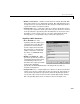
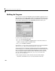
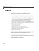
Analog Output (DAC) Block Parameters
• Base I/O Address —The
beginning of the I/O address
space assigned to the board. The
value specified here must match
the board’s configuration. Note
that this parameter is a
hexadecimal number and must be
enteredinthedialogasa
MATLAB string (e.g.,
'0x300').
• Analog Output Range —This
parameter specifies the output
range settings of the DAC section
of the I/O board. Typically,
unipolar ranges are between
[0 10] volts and bipolar ranges
are between
[-10 10] volts. Refer
to the DAS-1600 documentation
for other supported output
ranges.
• Initial Output(s) —This
parameter can be specified either
as a scalar or as an N element vector, where N is the number of channels. If
a single scalar value is entered, the same scalar is applied to output. The
specified initial output(s) is written to the DAC channels in the
mdlInitializeConditions function.
• Final Output(s) — This parameter is specified in a manner similar to the
Initial Output(s) parameter except that the specified final output values are
written out to the DAC channels in the
mdlTerminate function. Once the
generated code completes execution, the code sets the final output values
prior to terminating execution.