
User`s guide


Device Driver Blocks
9-11
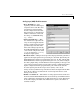
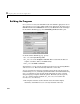
Analog Input (ADC) Block Parameters
• Base I/O Address —The
beginning of the I/O address space
assigned to the board. The value
specified here must match the
board’s configuration. Note that
this parameter is a hexadecimal
number and must be entered in
the dialog as a MATLAB string
(e.g.,
'0x300').
• Analog Input Range —This
two-element vector specifies the
range of values supported by the
Analog to Digital Converter. The
specified range must match the
I/O board’s settings. Specifically,
the DAS 1600/1400 Series boards
can be switch configured to either
[0 10] for unipolar or [-10 10]
for bipolar input signals.
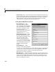
• Hardware Gain — This parameter specifies the programmable gain that is
applied to the input signal before presenting it to the ADC. Specifically, the
DAS-1601/1401 boards have programmable gains of 1, 10, 100, and 500. The
DAS-1602/1402 boards have programmable gains of 1, 2, 4, and 8. Configure
the Analog Input Range and the Hardware Gain depending on the type and
range of the input signal being measured. For example, a DAS-1601 board in
bipolar configuration with a programmable gain of 100 is best suited to
measure input signals in the range between [±10v] ÷ 100 = ±0.1v.
Voltage levels beyond this range will saturate the block output form the ADC
block. Please adhere to manufacturers’ electrical specifications to avoid
damage to the board.
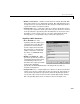
• Number of Channels — The number of analog input channels enabled on
the I/O board. The DAS-1600/1400 Series boards offer up to 16 ADC channels
when configured in unipolar mode (8 ADC channels if you select differential
mode). The output port width of the ADC block is equal to the number of
channels enabled.