
User`s guide

Implementation Overview
9-5
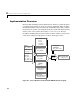
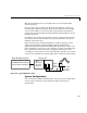
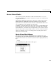
This diagram illustrates the code modules that are used to build a DOS
real-time program.
To execute the code in real time, the program runs under the control of an
interrupt driven timing mechanism. The program installs its own interrupt
service routine (ISR) to execute the model code periodically at predefined
sample intervals. The PC-AT’s 8254 Programmable Interval Timer is used to
time these intervals.
In addition to the modules shown in Figure 10-1, the DOS run-time interface
also consists of device driver modules to read from and write to I/O devices
installed on the DOS target.
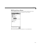
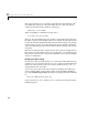
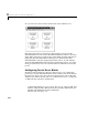
Figure 9-2 shows the recommended hardware setup for designing control
systems using Simulink, and then building them into DOS Realtime
applications using the Real-Time Workshop. The figure shows a robotic arm
being controlled by a program (i.e., the controller) executing on the Target-PC.
The controller senses the arm position and applies inputs to the motors
accordingly, via the I/O devices on the target PC. The controller code executes
on the PC and communicates with the apparatus it controls via I/O hardware.
Figure 9-2: Typical Hardware Setup
System Configuration
You can use the Real-Time Workshop with a variety of system configurations,
as long as these systems meet the following hardware and software
requirements.
I/O Devices
Position
Sensor
Output
Motor
Drive
DOS
Executing
Real-time
Program
Control
Target PC
Host Workstation PC
Running Windows 95/NT
with MATLAB, Simulink
and Real-Time Workshop
A/D D/A