
User`s guide
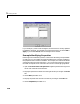


Table Of Contents
- Getting Started
- Using Instrumentation in a Model
- Categories of ActiveX Controls
- Placing ActiveX Controls in a Different Window
- Library Reference
- Index

Connecting Blocks in a Model
2-3
Connecting Blocks in a Model
Before you connect a Dials & Gauges Blockset block with other blocks, you
should know whether it is meant to be an input device (with an output
connection), or an output device (with an input connection). Dials & Gauges
Blockset blocks are initially drawn with both an inport and an outport, but
Simulink removes unused ports when the simulation starts running or when
you update the block diagram.
To determine whether a Dials & Gauges Blockset block is meant to be used as
an input or output device, right-click on the block and select the
Block
Parameters
option.
Note If you built your own ActiveX control by customizing the generic
ActiveX Control block, then another way to display the custom block’s
Block
Parameters dialog box is to double-click on the border of the block.
In the
Block Parameters dialog box, the Connections field determines the
type of connection the block currently uses:
•
Input indicates that the block has an inport and receives a signal. The Input
property
parameter indicates the block’s property whose value is changed
by the input.
•
Output indicates that the block has an outport and outputs a signal. The
Output property parameter indicates the block’s property whose value is
output.
•
Both indicates that the block has an inport and an outport and receives and
outputs a signal.
•
Neither indicates that the block has neither an inport nor an outport.
To specify a connection different from the block’s default setup, choose the
Connection type and make sure that the Input property and Output
property
fields are filled in with the appropriate property name. See
“Summary of Dialog Box Fields and Check Boxes” on page 3-29 for information
about the other fields and check boxes. You can also press the
Help button to
find out about other parameters.