
User guide
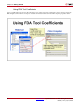
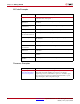
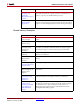
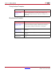
Table Of Contents
- Return to Menu
- System Generator for DSP
- Table of Contents
- About This Guide
- Introduction
- Installation
- Release Information
- Getting Started
- Introduction
- Lesson 1 - Design Creation Basics
- The System Generator Design Flow
- The Xilinx DSP Blockset
- Defining the FPGA Boundary
- Adding the System Generator Token
- Creating the DSP Design
- Generating the HDL Code
- Model-Based Design using System Generator
- Creating Input Vectors using MATLAB
- Lesson 1 Summary
- Lab Exercise: Using Simulink
- Lab Exercise: Getting Started with System Generator
- Lesson 2 - Fixed Point and Bit Operations
- Lesson 3 - System Control
- Lesson 4 - Multi-Rate Systems
- Lesson 5 - Using Memories
- Lesson 6 - Designing Filters
- Additional Examples and Tutorials
- Index
System Generator for DSP Getting Started Guide www.xilinx.com 97
UG639 (v 12.2) July 23, 2010
Additional Examples and Tutorials
System Generator Demos
System Generator for DSP provides the capability to model and implement high-
performance DSP systems in field- programmable gate arrays (FPGAs) using Simulink.
The Xilinx Blockset contains bit and cycle-true models of arithmetic and logic functions,
memories, and DSP functions for digital filtering, spectral analysis, and digital
communications. System Generator converts a Simulink model of Xilinx blocks into an
efficient hardware implementation that combines synthesizable VHDL and intellectual
property blocks that have been hand-crafted to run efficiently in FPGAs.
Included with the tool are numerous demonstration designs that highlight key features
and tool capabilities, as well as general good design practices using real-world design
applications. These designs may be accessed from the System Generator demo page. Enter
the following command at the MATLAB prompt:
demo blocksets xilinx